background image

CONNECTIONS

PRECAUTIONS

FEA

TURES

PREP

ARA

TION

TROUBLE-

SHOOTING

OTHERS

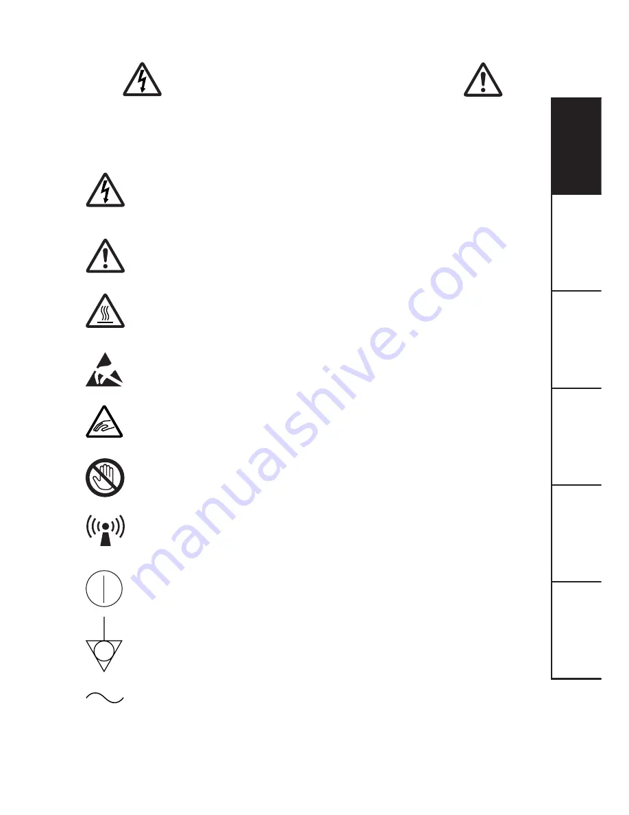
The lightning flash with arrowhead symbol, within an equilateral triangle, is
intended to alert the user to the presence of uninsulated “dangerous voltage” within
the product's enclosure that may be of sufficient magnitude to constitute a risk of
electric shock.

The exclamation point within an equilateral triangle is intended to alert the user to
the presence of important operating and maintenance (servicing) instructions in the
literature accompanying the appliance.

The “Caution, hot surface” symbol indicates that the marked item may be hot and
should not be touched.

The “Electro Static Discharge (ESD) warning” symbol indicates that trouble (in-
cluding equipment malfunction) due to static electricity may occur in certain
conditions.

This symbol indicates the possibility that the user may get his/her fingers caught
in the door, slot, or other mechanism.

This symbol indicates the possibility that the user may get injured when he/she
touches certain areas of the product.

The “Nonionizing radiation” symbol

The “ON/OFF” symbol indicates connection to or disconnection from the mains,
at least for mains switches.

The “Equipotentiality” symbol identifies the terminals connected each other.  The
potential of various parts of equipment or of a system is equalized.

The “Alternating current” symbol indicates that the equipment is suitable for
alternating current only.

RISK OF ELECTRIC SHOCK 

DO NOT OPEN.

TO REDUCE THE RISK OF ELECTRIC SHOCK,DO NOT REMOVE COVER (OR
BACK)
NO USER-SERVICEABLE PARTS INSIDE. REFER SERVICING TO QUALIFIED
SERVICE PERSONNEL.

CAUTION:

Содержание CP-30DW

Страница 1: ...the EC Directive 89 336 EEC 73 23 EEC 93 42 EEC and 93 68 EEC The electro magnetic susceptibility has been chosen at a level that gains proper operation in residential areas on business and light industrial premises and on small scale enterprises inside as well as outside of the buildings All places of operation are characterised by their connection to the public low voltage power supply system ...

Страница 2: ...nformation This class A digital apparatus complies with Canadian ICES 003 CLASSIFIED BY UNDERWRITERS LABORATORIES INC WITH RESPECT TO ELECTRIC SHOCK FIRE AND MECHANICAL HAZARDS ONLY IN ACCORDANCE WITH UL60601 1 AND CAN CSA C22 2 No 601 1 Indications according to IEC60601 1 1 Functions and intended usage of this product This product receives signals from diagnostic imaging equipment or a personal c...

Страница 3: ...in cluding equipment malfunction due to static electricity may occur in certain conditions This symbol indicates the possibility that the user may get his her fingers caught in the door slot or other mechanism This symbol indicates the possibility that the user may get injured when he she touches certain areas of the product The Nonionizing radiation symbol The ON OFF symbol indicates connection t...

Страница 4: ...2 0 standard High speed requirements and USB IF USB Implementers Forum approved This product is to be employed with medical equipment just for reference purpose not for medical diagnostic purpose Your MITSUBISHI ELECTRIC product is designed and manufactured with high quality materials and components which can be recycled and reused This symbol means that electrical and electronic equipment at thei...

Страница 5: ... of the product with one hand 3 Thenecessaryworkforinstallation maintenance orinspectionshouldbeperformedunder the above mentioned conditions 4 Itisrecommendedthatallstaffinvolvedintheworkinwhichtheymaytouchtheareasidentified with the ESD warning symbol should receive an explanation of the ESD warning symbol and training on the ESD precautionary procedures 5 Required minimum contents in the explan...

Страница 6: ...61000 4 11 Power frequency 50 60 Hz magnetic field EN 61000 4 8 EN 60601 test level 6 kV contact 8 kV air 2 kV for power supply lines 1 kV for input output lines 1 kV line s to line s 2 kV line s to earth 5 UT 95 dip in UT for 0 5 cycle 40 UT 60 dip in UT for 5 cycles 70 UT 30 dip in vT for 25 cycles 5 UT 95 dip in UT for 5 sec 3 A m Electromagnetic environment guidance Floors should be wood concr...

Страница 7: ...ransmitters as determined by an electromagnetic site survey a should be less than the compliance level in each frequency range b Interference may occur in the vicinity of equipment marked with the following symbol Compliance level 3 Vrms 3 V m NOTE1 At 80 MHz and 800 MHz the higher frequency range applies NOTE2 These guidelines may not apply in all situations Electromagnetic propagation is affecte...

Страница 8: ...using the equation applicable to the frequency of the transmitter where P is the maximum output power rating of the transmitter in watts W according to the transmitter manufacturer NOTE1 At 80 MHz and 800 MHz the separation distance for higher frequency range applies NOTE2 These guidelines may not apply in all situations Electromagnetic propagation is affected by absorption and reflection from str...

Страница 9: ... with USB interface 11 Setting DIP switches 11 Before operation 12 16 Paper ink ribbon set 12 Loading print paper 12 13 Loading ribbon cartridge 14 Usage and storage of paper ink ribbon set 15 Installing printer driver 16 Troubleshooting 17 20 Indication on the status display countermeasures 17 Overcoming paper jams 18 Before calling for service 19 Repairing a torn ink ribbon 20 Cleaning 21 Spec o...

Страница 10: ...llow it to become pinched or cut If the power cord becomes damaged replace it immediately to avoid shock hazard or electrical fire When the power cord is replaced use the same type as originally supplied it is designed to reduce interference to radio TV reception When unplugging the power cord hold the plug and remove it carefully KEEP THE UNIT DRY DO NOT PLACE WATER OR OTHER LIQUID CONTAINERS ON ...

Страница 11: ...our hands will contaminate the head and may spoil the prints CONNECTING CABLES Use the power cord supplied with the printer INSTALLATION LOCATIONS MAINTAIN GOOD VENTILATION Ventilation slots and holes are provided on the rear sides and bottom of this unit Place the unit on a hard and level surface and keep a space between the unit and the walls to ensure proper ventilation When installing the unit...

Страница 12: ...t head like a video head wears out When it is worn it becomes hard to print out fine details of the picture If it occurs consult your dealer about having the head replaced CONNECTING DEVICES Read thoroughly the Safety Notices Cautions and Operating Precautions of the instruction booklets for the other devices connected with the unit CAUTION ON RELOCATING When transporting the unit make sure it is ...

Страница 13: ...hat the safety certification of the ACCESSORY has been performed in accordance to the appropriate EN60601 1 and or EN60601 1 1 harmonized national standard The transportation and storage environmental conditions are Temperature 20 C 60 C 4 F 140 F Humidity 30 80 RH Atmospheric pressure 50 kPa 106 kPa Note The above transportation environmental conditions indicate the storage environmental conditio...

Страница 14: ...p photo images PRODUCT OUTLINE The digital printer CP30DW uses the thermal dye sublimation printing system This printer is able to print digital color images on the paper This printer is connected to a host computer via USB interface Digital images such as CT MRI ultrasound and CR images transmitted from the host computer is printed via USB interface This printer creates prints electronically main...

Страница 15: ...hion containing the accessories out of the box Be careful not to drop the accessories DIGITALCOLORPRINTER MODEL CP30DW OPERATION MANUAL THISOPERATIONMANUALISIMPORTANT TOYOU PLEASEREADITBEFOREUSINGYOUR DIGITALCOLORPRINTER CD ROM Power cords Paper cassette UNPACKING UNPACKING 4 4 4 4 4 Unwrap the packing NOTE When you lift up this unit do not insert your hand to the print outlet 2 2 2 2 2 CONTENTS A...

Страница 16: ...ata transfer blinking 2 During printing blinking slowly 3 After printed paper ejection illuminates for 5 seconds 4 Occurence of error blinking rapidly 5 3 2 7 6 8 9 10 1 DATA RIBBON PAPER ALARM 11 12 13 14 15 4 STATUS DISPLAY FEATURES FUNCTIONS 5 5 5 5 5 POWER BUTTON Press to turn on and off the power Each time this button is pressed ON OFF is switched 6 6 6 6 6 RIBBON CARTRIDGE LOADING SLOT A fla...

Страница 17: ...CATOR This indicator illuminates for error conditions See page 17 F F F F F STATUS INDICATOR This indicator shows the remaining amount of the ink ribbon error status and print status It illuminates during printing as shown below Each time a ribbon cartridge is ejected or loaded the counter of the ink ribbon remaining amount on the status indicator is set to the initial value For error indications ...

Страница 18: ...it to a device equipped with USB interface such as a personal computer See page 11 for connection 2 2 2 2 2 AC LINE SOCKET Connects to the provided power cord Insert the cord firmly 3 3 3 3 3 POTENTIAL EQUALIZATION CONNECTOR Connect this terminal and that of the connected device This terminal is used to equalize the potential of the device connected to the unit Be sure to make this connection for ...

Страница 19: ...No 1 is enable 2 OFF Set this switch to OFF ON 3 OFF Set this switch to OFF ON 4 OFF Set this switch to OFF ON 5 OFF Set this switch to OFF ON 6 OFF This unit prints images according to the printing mode setting of the printer driver 2 ON This unit prints images in power save mode regardless of the printing mode setting of the printer driver 2 7 OFF Set this switch to OFF ON 8 OFF Set this switch ...

Страница 20: ...to the size of the paper to be loaded Do not force paper that is too long or too wide into the paper cassette NOTE Use the paper cassette designed for this unit only 1 1 1 1 1 Remove the tray cover of the paper cassette 2 2 2 2 2 Adjust the paper cassette to secure the paper Raise the plate in the cassette to use S size paper Keep the plate laid flat to use L size paper 3 3 3 3 3 Take the print pa...

Страница 21: ...placed on the top of the paper NOTE You can load only one package of print paper supplied as paper ink ribbon set 6 6 6 6 6 Set the tray cover onto the paper cassette 7 7 7 7 7 Load the paper cassette in the printer 8 8 8 8 8 When using L size paper raise the stopper on the tray cover CAUTION Do not put your hand inside the product from the paper cassette loading slot or ribbon cartridge loading s...

Страница 22: ...ribbon cartridge into the ribbon cartridge loading slot Be sure to hold the handle Insert the ribbon cartridge in the direction of the arrow with the marking of TOP SIDE up The installation of print paper and ribbon cartridge is completed NOTE Do not leave more than 15 sheets of print paper on the print outlet Be sure to install the paper cassette properly If it is not installed properly a paper j...

Страница 23: ...ombination as provided in the box Use of wrong combination may cause malfunction 2 2 2 2 2 AFTER PRINTING When the printed paper is touched with a wet hand the print may be discolored Fading may occur if the print face is exposed to organic chemical agents which may affect print paper e g alcohol ester ketene based Fading will be accelerated upon contact with PVC based materials e g adhesive tapes...

Страница 24: ... installing the printer driver Windows 2000 and Windows XP are the registered trademarks of Microsoft Corporation in the U S A and other countries BEFORE OPERATION Printer driver CPD30X A printer driver is required to print the data from a personal computer connected with this unit The printer driver for Windows is supplied with this unit ...

Страница 25: ...bbon cartridge The actual combination of ribbon cartridge and print paper is inconsistent with the settings made by a personal computer Set the personal computer according to the actual combination of ribbon cartridge and print paper Print paper of wrong size is loaded Use the ribbon cartridge and print paper supplied in the same package Paper misfeed Unload the paper cassette and load it again Pa...

Страница 26: ...the dial inside the access cover to remove the jammed paper NOTE Turn the dial in the direction of the arrow Never turn it in the opposite direction It may cause malfunction Contact your dealer if you can not clear the paper jam per above instruction 6 6 6 6 6 Close the access cover 7 7 7 7 7 Load the paper cassette 8 8 8 8 8 Load the ribbon cartridge Remove slack the ink ribbon Hold the handle to...

Страница 27: ...ctly Check the status display Refer to INDICATION ON THE STATUS DISPLAY COUNTERMEASURES page 17 Is the status indicator blinking When the status indicator keeps blinking slowly the temperature of the thermal head may get high Wait until the temperature drops to a level where printing becomes available This unit does not print any images sent Is the power of this unit turned on from the computer Ar...

Страница 28: ...lat clean surface 2 2 2 2 2 Place a piece of transparent adhesive cellophane tape on the center of the ink ribbon REPAIRING A TORN INK RIBBON 3 3 3 3 3 Wind the gear in the direction of the arrow so that the cellophane tape is not seen and the ink ribbon is stretched taut 4 4 4 4 4 Install the repaired ribbon cartridge in the printer ...

Страница 29: ...URES PREPARATION TROUBLE SHOOTING OTHERS CLEANING Clean the thermal head using the cleaning kit for CP30 option to maintain stable printer operation and extend the printer s life Please ask your dealer about the cleaning kit CLEANING ...

Страница 30: ...ower consumption 1 5 A AC120V 50 60Hz during printing 0 2A when not printing 0 9A AC220 240V 50 60Hz during printing 0 2A when not printing Operating conditions Temperature 5 C 40 C 41 F 104 F Humidity 30 80 RH No dewing Atmospheric pressure 70 kPa 106 kPa Transportation and Temperature 20 C 60 C storage conditions Humidity 30 80 RH No dewing Atmospheric pressue 50 kPa 106 kPa Operation altitude W...

Страница 31: ... size 50 Color print 4 packs contained 2 2 2 2 2 CLEANING KIT FOR CP30 SERVICE INFORMATION Before requesting service please review this operation manual to correct minor complaints If you are unable to correct the problem consult your MITSUBISHI Dealer or MITSUBISHI Service Department DO NOT ADJUST ANY CONTROLS NOT DESCRIBED IN THIS OPERATION MANUAL DO NOT REMOVE THE PROTECTIVE ENCLOSURE OF THIS U...

Страница 32: ......

Отзывы: