[
IV
Outlines and Dimensions ]
- 8 -
HWE18160
GB
IV
Outlines and Dimensions
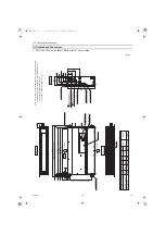
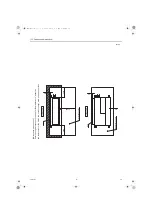
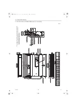
[1] Outlines and Dimensions
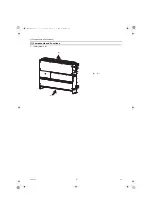
1. PFFY-P20, 25, 32, 40, 50, 63VMC-E Bottom suction ꞏ wall mounting
Unit: mm
Front
Bottom view
T
op view
view
Right side
view
Air inlet
Air outlet
Duct mounting holes
W
all mounting holes
Duct mounting holes
(Power source)
(T
ransmission)
(Power source wiring)
(T
ransmission wiring)
(Gravity drain)
Note 1. Use an M10 screw for the wall and floor mounting bolt (field supply).
2. This drawing is for PFFY-P63VCM-E model, which have 4 fans.
PFFY-P40·50VCM-E models have 3 fan.
PFFY-P20·25·32VCM-E models have 2 fan.
DE
F
AC
B
2
Liquid pipe
ø9.52
ø15.88
900
1100
1
Gas pipe
PFFY-P40
·50VCM-E
PFFY-P63VCM-E
956
1156
756
1002
1202
802
800
1000
600
9
11
7
700
PFFY-P20
·25
·32VCM-E
Model
ø6.35
ø12.7
860
1060
660
A
B(W
all mounting hole pitch)
C
23
51
100
100×(E-1)=F
D(Duct)
30
20
2×E-ø2.9 holes
50.5
10
528(Wall mounting hole pitch)
4-14×30 Slot
Drain pipe (O.D.ø32)
2×2-ø2.9 holes
150
25
200
100
15
655
615
23
94
65
172
98
274
136.5
100
22
Brazing connection (liquid)
Brazing connection (gas)
T
erminal block
T
erminal block
Knockout hole ø28
Knockout hole ø28
Air filter
Control box
2 Refrigerant piping
1 Refrigerant piping
HWE18160.book 8 ページ 2019年2月18日 月曜日 午前9時59分
Содержание CITY MULTI PFFY-P20VCM-E
Страница 1: ......
Страница 5: ...HWE18160 GB HWE18160 book 2 ページ 2019年2月18日 月曜日 午前9時59分 ...
Страница 39: ......


