background image

28MT Multi-Tool

3

Original Instructions Version December 15

Replacing the Nylon Cord

Check to see if the nylon head is damaged before replacing the cord. If you can see serious traces 
of wear or damage, you must replace the complete nylon head.

1. Stop the engine.
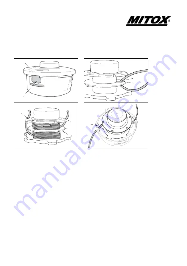
2. Open the nylon head by pushing on the catch, (a), and lifting the cover (b).
3. Pull the bobbin out of the nylon head and take out the rest of the nylon cords.
4. Cut  a new length of cord, 2.4mm Ø and 5 metres long. 
5. Fold the new cord in half and place the centre of the fold (c) into the clip (d) in the empty bobbin. 
6. Wind the line in the direction of the arrows on the bobbin, with half of the line above and half 
below the divider (e). Maintain an even and firm tension onto the bobbin, being careful not to twist 
the line.
6. After winding the cord, insert both ends into the notches on the bobbin, (f).
7. Put the filled bobbin back into the carrier. Release the cords from the notches in the bobbin 
and place them into the eyelets in the carrier (g). The cords should stick out appx 15 cm either 
side.  
8. Refit the spool cover (b), ensuring it is securely clicked into place.

Never use a cutting device other than those supplied by the manufacturer. (Steel cord is never 
allowed)  Always use original spare parts in order to benefit from continuous warranty.

(a)

(b)

(g)

(f)

(e)

(f)

(c)

(d)

Содержание 28MT

Страница 1: ...sion December 15 Assembly of the Brushcutter The blade fitted to the guard is sharp and can cause injury always wear gloves Installing the Guard Place the Brushcutter with the head facing down Fit the shield using the bracket and 2 X Torx screws ...

Страница 2: ... RESULT Rotate the gear box shaft until the hole in the holder A lines up with the slot in the metal guard Insert an Allen key or screwdriver into the hole in the gearbox cover and into holder A Place the 3 tooth blade on the holder A centering the blade on the raised centre Fit the holder B over the blade Fit the domed nut protector C over holder B and the blade Fit the nut anti clockwise turn le...

Страница 3: ...he empty bobbin 6 Wind the line in the direction of the arrows on the bobbin with half of the line above and half below the divider e Maintain an even and firm tension onto the bobbin being careful not to twist the line 6 After winding the cord insert both ends into the notches on the bobbin f 7 Put the filled bobbin back into the carrier Release the cords from the notches in the bobbin and place ...

Страница 4: ... gear box shaft until the hole in the holder A lines up with the slot in the metal guard Insert an Allen key or screwdriver into the hole in the gearbox cover and into holder A Screw the nylon head anti clockwise turn left onto the threaded shaft on the end of the gearbox Make sure that the nylon head is securely locked in position and remove the Allen key A A ...

Страница 5: ...sition 3 Loosen the clamp by turning the handle 4 Insert the attachment shaft lining up the locking hole with the locking pin Twist the locking pin 5 to release it from the outer position You may need to twist the attachment shaft to ensure that the locking pin engages with the locking hole 6 Tighten the clamp by turning the handle 7 Clamp Attachment shaft Locking hole Locking pin 1 2 3 4 5 7 6 ...

Страница 6: ...educe the engine speed so the engine idles Make sure that the cutting head has stopped rotating switch off the engine and remove the material Put the brushcutter on the ground and check that the cutting head has not been damaged If necessary change the cutting head If the head is only wrapped by vegetation remove by hand and clean the cutting head Always wear safety gloves for this operation and e...

Страница 7: ... gear boxes apply 2 or 3 pumps of grease every 15 hours of operation a Specification EX BC When used as a Brushcutter Weight Power Unit Attachment 6 51kg Weight Attachment Only 1 88Kg Reduction ratio 22 17 Cutting head Cutting width 3 tooth blade 255mm Nylon head 415mm 3 tooth blade thickness 1 4mm Cutting line diameter 2 4mm Max blade rotation speed 7500 rpm min 1 Rotation direction Counter clock...

Страница 8: ...28MT Multi Tool 8 Original Instructions Version December 15 Parts Diagram Body ...

Страница 9: ...MITBC431DJ 03 03 7 LOCK KNOB 13 MIGB T923 M6 NUT M6 14 MITBC431DJ 03 03 3 LOCK ASSY 15 MITBC431M 03 01 02 DRIVE SHAFT 16 MITBC431M 03 01 00 EXTENSION ASSEMBLY 17 MITBC431DJ 03 01 2 LIMIT SLEEVE 18 MITBC431DJ 03 03 00 COUPLING ASSEMBLY 19 MIGB T2671 2 M5X25 SCREW M5X25 20 MIGB T2671 2 M5X12 SCREW M5X12 21 MIGB T5781 M6X50 BOLT M6X50 22 MIGB T96 M6 WASHER M6 23 MITBC431DJ 03 03 7 LOCK KNOB 24 MIGB T...

Страница 10: ...ER 43 MITBC431D 04 00 5 BLADE CLAMP UPPER 44 MITBC431D 04 00 8 NUT PROTECTOR 45 MIGB T6177 2 M10X1 25 NUT 10X1 25 LH 46 MIGB T70 1 M6X12 SCREW M6X12 47 MIGB T2671 2 M6X12 SCREW M6X12 48 MIGB T2671 2 M6X25 SCREW M6X25 49 MITBC431D 06 01 1 SKIRT 50 MIGB T845 ST4 8X13 TAPPING SCREW ST4 8X13 51 MITBC431D 06 00 2 LINE CUTTER 52 MITBC431D 06 02 00 DEBRIS GUARD 53 MITBC431D 06 00 3 SLEEVE 54 MITBC430D 06...

Страница 11: ...G 71 MITBC431S 05 02 8 WIRE A 72 MITBC431S 05 02 9 WIRE B 73 MITBC431S 05 02 10 CONDUIT 74 MITBC431S 05 02 7 THROTTLE CABLE 75 MIGB T2671 2 M5X14 SCREW M5X14 76 MIGB T845 ST3 5X9 5 ST SCREW 3 5X9 5 77 MIGB T845 ST4 2X10 ST SCREW 4 2X10 78 MIGB T2671 2 M5X14 SCREW M5X14 79 MITBC431S 05 02 4 THROTTLE TRIGGER 80 MIYD38 3 01 11 04 00 ON OFF SWITCH 81 MITBC431S 05 02 3 LOCK TRIGGER 82 MITBC431S 05 02 6...

Страница 12: ...e Incorrect assembly adjustment or operation of the product Spare parts that are subject to wear e g safety parts blades blade supports bearings cables guards deflectors spark plugs air filters etc Neither does warranty extend to Freight and packing costs Use of non genuine spare parts i e those from another manufacturer Use of the machine for any other purpose than that for which it was designed ...

Отзывы: