


I
NSTALLING
B
OARDS
AND
C
ABLING
19
21/1531-ASP11301 Uen B3 2016-02-17
Figure 12: Example of Removing the Negative Battery Conductor (A) and an
Interconnecting Bridge (B)
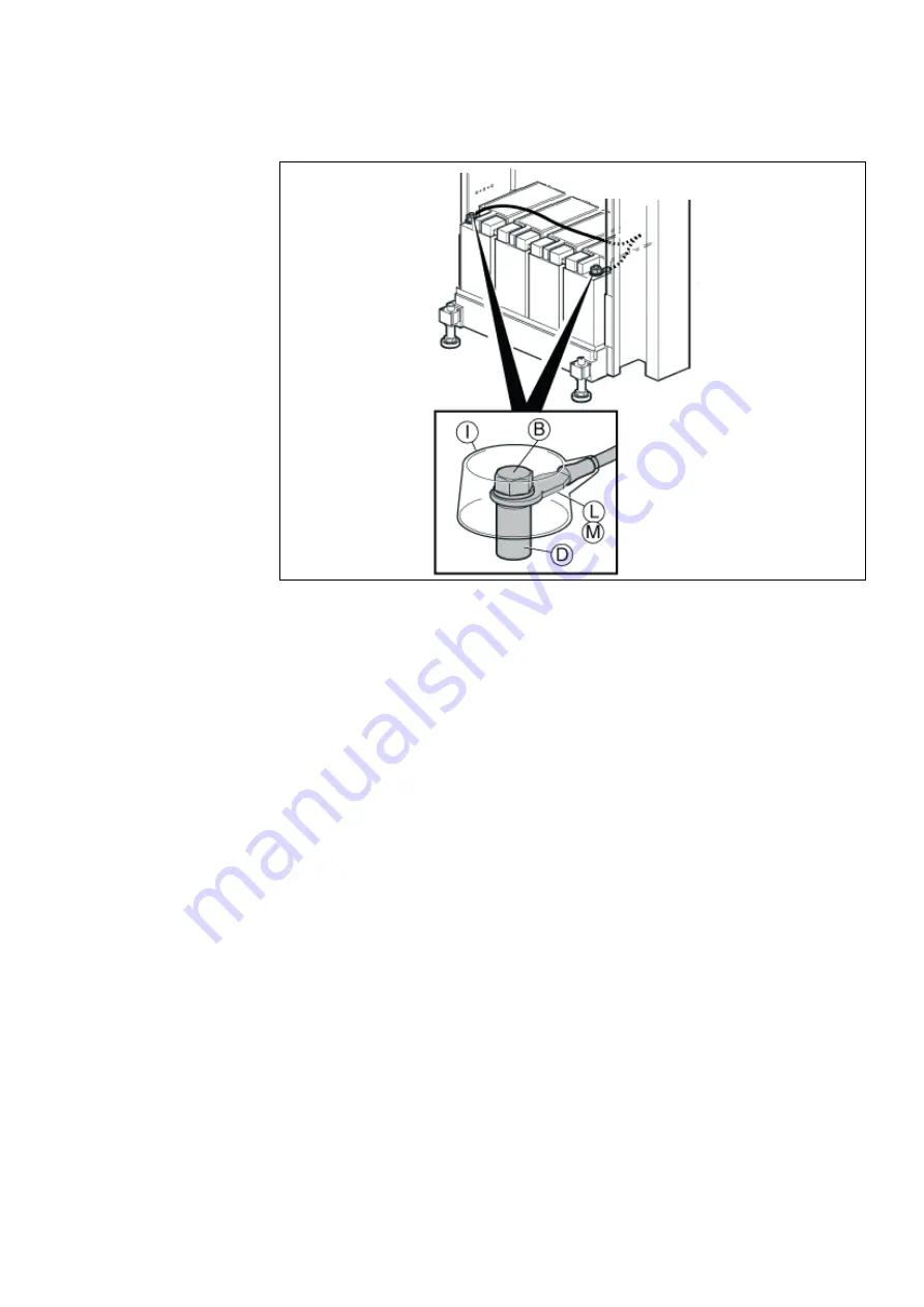
Figure 13: Connecting the Batteries
General battery connection:
1.
Connect the cable lug (L) of the grey cable supplied with the batteries mounting
set (BKB 201 003/1) to the red plus pole (D) of the rightmost battery block, see
Figure 13: Connecting the Batteries on page 19.
2.
Fasten the screw (B) to secure the cable lug and press down the cover (I) on the
red plus pole (D).
3.
Connect the grey positive (+0V) DC supply cable (L) to the positive bus
bar/connector according suppliers documentation. For connection in BZA10911,
the 2U AC/DC, see document BCG.00075 for User manual, and
1/1531-BZA10911 for Quick Install Guide.
4.
Connect the cable lug (M) of the black cable to the minus pole (D) of the leftmost
battery block, see Figure 13: Connecting the Batteries on page 19.
5.
Fasten the screw (B) to secure the cable lug and press down the cover (I) on the
black minus pole (D).
6.
Connect the black negative (-48V) DC supply cable (M) to the appropriate nega-
tive DC connection on the AC/DC-unit. For connection in BZA10911, the 2U
AC/DC see document BCG.00075 for User manual, and 1/1531-BZA10911.
Battery connection for the
UK
:
1.
Connect the cable lug (L) of the blue cable part of the TSR 903 0113/1 cable to
the red plus pole (D) of the rightmost battery block, see Figure 13: Connecting
the Batteries on page 19.
2.
Fasten the screw (B) to secure the cable lug and press down the cover (I) on the
red plus pole (D).


