

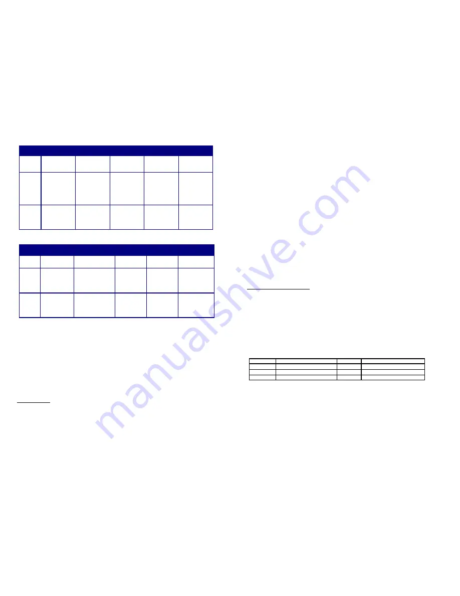
Table 1 - 25K MSL Version Switch functions and positions
Table 2 - 40K MSL Version Switch functions and positions
Switch 1
Switch 2
Switch 3
Switch 4
Switch 5
Func.
Main deployment
altitude selection
Dual Deploy
selection or
Redundant
Apogee
Mach delay timer
selection
Mach delay timer
selection
High or Low
range Main
deployment
On
Pos.
Stage 2 (J2/Main)
deploys at 1000
ft. (SW.5 OFF) or
800 ft. AGL
(SW.5 ON)
Redundant
apogee deploy-
ment operation
(Stage 2/Main
fires at apogee
and overrides
SW.1 & SW.5
setting)
4 seconds of
delay time is
added to the
mach delay timer
total
8 seconds of
delay time is
added to the
mach delay timer
total
Lo-range Stage 2
(J2) deployment
altitudes are
selected (800 or
300 ft) based on
SW.1
Off
Pos.
Stage 2 (J2/Main)
deploys at 500 ft.
(SW.5 OFF) or
300 ft. AGL
(SW.5 ON)
Standard two
stage deployment
operation (Stage
2/Main altitude
selected by SW.1
& SW.5 settings)
0 seconds of
delay is added to
the mach delay
timer total
0 seconds of
delay is added to
the mach delay
timer total
Hi-range Stage 2
(J2) deployment
altitudes are
selected (1000 or
500 ft) based on
SW.1
Switch 1
Switch 2
Switch 3
Switch 4
Switch 5
Func.
Main deploy-
ment altitude
selection
Dual Deploy selection
or Redundant Apogee
Mach delay
timer selection
Mach delay
timer selection
High or Low range
Main deployment
On
Pos.
Stage 2 (J2/
Main) deploys at
2500 ft. (SW.5
OFF) or 2000 ft.
AGL (SW.5 ON)
Redundant apogee
deployment operation
(Stage 2/Main fires at
apogee and overrides
SW.1 & SW.5 set-
ting)
10 seconds of
delay time is
added to the
mach delay
timer total
15 seconds of
delay time is
added to the
mach delay
timer total
Lo-range Stage 2
(J2) deployment
altitudes are
selected (2000 or
1000 ft) based on
SW.1 position
Off
Pos.
Stage 2 (J2/
Main) deploys at
1500 ft. (SW.5
OFF) or 1000 ft.
AGL (SW.5 ON)
Standard two stage
deployment operation
(Stage 2/Main altitude
selected by SW.1 &
SW.5 settings)
0 seconds of
delay is added
to the mach
delay timer total
0 seconds of
delay is added
to the mach
delay timer total
Hi-range Stage 2
(J2) deployment
altitudes are
selected (2500 or
1500 ft) based on
SW.1 position
IMPORTANT – The Mach Delay and High/Low range settings (SW. 3/4/5) MUST be made prior to powering up the unit.
They are read at power up ONLY. Set ALL switch positions prior to turning the unit on.
Mach Delay timer
For high-performance rocket flights approaching or exceeding the speed of sound (mach), the unit can be configured to employ
a time delay just after lift-off is detected. This time delay prevents the possibility of premature apogee detection caused by the
high/low pressure effects present along the rocket airframe during transition into and out of mach. During the time delay, all
barometric samples from the sensor are ignored so these pressure effects cannot falsely trigger the apogee charge. After the
expiration of time delay, normal barometric sampling resumes. The unit can be programmed for 4/10 seconds (SW.3 ON / SW.4
OFF), 8/15 seconds (SW.3 OFF / SW.4 ON), or 12/25 seconds (SW.3 ON / SW.4 ON) of total delay. It is recommended to use
the mach delay at velocities of 0.8 mach or above.
Deployment methods / Standard two-stage & Single-Stage (via Redundant Apogee mode)
Two-stage recovery of high power rockets is preferable as previously described in the "Overview" section of this document.
Single-stage deployment has its own set of advantages when the launch site size or weather conditions permit main parachute
deployment at apogee. They are much simpler in design and are simpler to operate and prepare. Redundant apogee mode
fires both charges at apogee (1 sec apart).
Modes of Operation
The RRC²X has several distinct modes throughout the course of its normal operation. These modes of operation are easily
identified by the piezo beeper and the status LED.
Power-up switch position annunciation
After initially powering on the RRC²X unit, it will annunciate (beep) the positions of all 5 switches in numerical order (1 through 5)
with a series of '0's and '1's. A zero is a long beep, a 1 is a short beep A switch in the OFF position will beep as a '0', and a
switch in the ON position will beep as a '1'. The LED flashes at a fast rate of 5 times per second. This annunciation allows you
to double check the altimeter switch settings once inside the rocket.
Baro initialization mode
After the switch position annunciation, the unit goes through a 15-second initialization and start-up delay. The LED flashes at a
fast rate of 5 times per second. There is no audible sound from the piezo beeper. This start-up delay allows stabilization of the
electronics and establishes an initial barometric history.
Pre-launch mode
After the 15-second power up and initialization delay, the unit goes into the pre launch mode. The LED will flash at a slow 2
second rate, and the piezo beeper will indicate the continuity of the ejection charges as follows:
Long Beep
No continuity on either channel
1 Short Beep
Continuity on channel 1
2 Short Beeps
Continuity on channel 2
3 Short Beeps
Continuity on channel 1 & 2
The unit also monitors the barometric sensor for a change of 300 feet in elevation to determine the launch of the rocket. After
this change, the unit transitions into mach delay mode (if selected) or apogee detection mode.
Mach Delay mode
When either SW. 3 or SW. 4 is in the ON position, the unit will enter the mach delay mode. The LED flashes again at its fast
rate of 5 times per second. There is no audible sound from the piezo beeper. After the expiration of the mach delay (if se-
lected), the unit transitions into apogee detect mode.
Apogee Detection Mode
At this point, the RRC²X has detected launch and is in flight. The LED continues to flash at its fast rate of 5 times per second.
The piezo beeper will beep at a fast rate of ½ second. During this mode the unit is sampling for apogee (indicated by an in-
crease in pressure). When this pressure increase is detected, the unit transitions into deployment mode.
Deployment mode
Now that the unit has detected apogee, it will fire the channel 1 (J1) output. The LED will continue to flash at its fast rate of 5
times per second. There is no output from the piezo beeper. If the unit was set to operate in standard dual deployment mode, it
will continue to sample barometric pressure until it reaches the designated main deployment elevation above the initial launch
elevation before firing the channel 2 (J2) output. Otherwise the unit is operating in redundant apogee mode, and it will then fire
the channel 2 output immediately following the channel 1 output. After the unit has fired both output channels, it transitions into
report mode.
Report mode
After deployment of the recovery system, the unit will report the peak altitude it measured during flight. The LED will continue to
flash at its fast rate of 5 times per second. The piezo beeper will continuously annunciate the peak altitude by beeping out the
individual digits of the measurement. Depending on the peak altitude, the unit will annunciate 3, 4, or 5 digits. For example,
let’s say the rocket flew to a peak altitude of 1230 feet. The unit would beep as follows:
Beep...pause…Beep, Beep…pause…Beep, Beep, Beep…pause…Beeeeeeeeeeep…long pause….(repeat)
Test Mode Operation and Diagnostics
The unit can also be placed into a test mode to verify the basic integrity of the unit, and also to ground test e-matches, igniters,
ejection charges, or recovery system designs. To place the unit into a test mode, toggle either SW. #1 or SW. #2 during the
power up and initialization period according to the test you'd like to run. Toggling SW. #1 will set the unit into input test mode.
Toggling SW. #2 will set the unit into output test mode The unit will continue to operate in the test mode selected until it is pow-
ered off.
IMPORTANT: After selecting a test mode, you must power off the unit prior to flight or additional testing.
Input Test mode
After toggling SW. #1, the unit will enter the input test mode. This mode verifies the integrity of all the inputs to the microproces-
sor. Whenever an input is in the ON position, the unit will beep out a digit to indicate operational integrity of the input (see Table
2). The test mode scans and reports the inputs starting with the lowest value first (SW. 1). Lower value switch positions and
inputs take priority over higher position switches and inputs.
There are several factors to consider when it comes to the con-
struction, mounting, wiring and arrangement of the RRC²X in your rocket airframe. Careful planning during the construction and
preparation of your rocket will improve your chances for a successful recovery.
Table 2 - Input Test mode beep indications
Output Test Mode
After toggling SW. 2, the unit will enter the output test mode. This mode can be used to test the integrity of both outputs (J1 and
J2) and to also ground-test your pyrotechnic e-match, igniter, flashbulb, ejection charge, or ground test deployment of your
entire recovery system. The test mode begins by beeping the piezo beeper at a fast rate of 5 beeps per second. After 10
seconds of countdown, the unit will fire the J1 output. This is followed immediately by firing the J2 output (this functions identical
to the deployment firing sequence used in the redundant apogee mode).
IMPORTANT: Always exercise caution when using live pyrotechnic charges in the output test mode.
Another useful accessory for testing the outputs are 12 volt DC panel lamps. The lamps will allow you to observe the proper
operation of the outputs without the use of pyrotechnic devices.
Barometric Limits Alarm
The unit also features a barometric limit alarm. This alarm mode is easily identified by the continuous actuation of the piezo
beeper. While the unit is in the pre-launch mode it tests the barometric sensor reading for basic integrity. If the reading is below
0' MSL or above 14000' MSL the alarm will sound. This extreme reading indicates a failed sensor (unless of course your at-
tempting to launch from those base elevations, in which case you cannot do so).
IMPORTANT: Do not fly the unit if it activates the baro sensor alarm.
1 Beep
SW. #1 in the ON position
5 Beeps
SW. #5 in the ON position
2 Beeps
SW. #2 in the ON position
6 Beeps
J1 continuity
3 Beeps
SW. #3 in the ON position
7 Beeps
J2 continuity
4 Beeps
SW. #4 in the ON position


