


4
We thank you for purchasing the shower cabin of MIRWELL trade mark and hope that
it will come up to all of your expectations.
The shower cabin can be used in apartments, houses or hotels – in all cases its
installation will be simple and safe, while using it will give you pleasure and bene
fi
t
your health.
Shower cabins of MIRWELL trade mark combine all of the latest designs developed by
our company, introduced in order to give this product even higher quality and make it
even more convenient in exploitation.
The product you have purchased is manufactured in compliance with modern
European technical standards, meets mandatory construction and sanitary standards.
All products of MIRWELL trade mark are manufactured in compliance with
requirements of the highest standards, which de
fi
ne all technical parameters of
shower cabins for sale in the European Union countries.
Please, read this installation and operation manual carefully in order to ensure the
safest and the most e
ff
ective installation, utilization and maintenance of the product.
Manufacturer reserves the right not to notify the end user about di
ff
erences in
structures between the obsolete model and the new, improved version of the shower
cabin; however, we are sure that this will not hamper your utilization of the product.
Thank you for the purchase!
DEAR CUSTOMERS!
GENERAL INFORMATION
The shower cabin is intended for hydrotherapeutic procedures.
The product has functions of manual shower, hydromassage and tropical shower,
hydromassage sprayers, electronic control panel, FM radio, fan, lighting.
Installation of hydromassage cabin must be conducted by quali
fi
ed specialist.
TECHNICAL FEATURES
• Used voltage 220 ± 10 %.
• Used water pressure 0.2-0.4 MPa, water discharge 8-12 l/min. Temperature of hot
water fed onto the cabin should not exceed 70°
С
. Installation of coarse water
fi
lters
is required.
• Level of canalization draining from
fl
oor up to tray must be at least 70 mm.
• Maximum load to the tray 210 kg.
• Mounting dimensions of hot and cold water pipeline 1/2” (15 mm), drainhole
diameter 1-1/2” (40 mm).
• Upon
fi
nishing to use the cabin it is necessary to put a switch to OFF position.
Upon
fi
nishing to use the cabin it is necessary to shut down feeding of cold and hot
water in the cabin.
EN
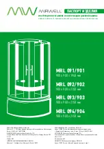
Содержание MRL 091/901
Страница 3: ...3...
Страница 11: ...11 5 SHOWER CABIN INSTALLATION A2 A6 M4 8 A1 2 2 2 4 A7 A8 A1 2 A2 A1 1 A6 A6 A6 A6 A7 A8...
Страница 12: ...12 6 SHOWER CABIN INSTALLATION Components of the middle panel may di er depending on the model...
Страница 13: ...13 SHOWER CABIN INSTALLATION 7 8 A9 A33 A9 3 A33 3 0 A10 12 A10...
Страница 14: ...14 SHOWER CABIN INSTALLATION 9 12 A 11 A12 A33 A12 6 A11 A11...
Страница 15: ...15 SHOWER CABIN INSTALLATION 10 A13 A14 A 1 3 4 A14 4 A25 2 A25...
Страница 17: ...17 SHOWER CABIN INSTALLATION 13 A9 A33 A12 A9 3 A12 6...
Страница 18: ...18 SHOWER CABIN INSTALLATION 14 A16 A16 A16...
Страница 19: ...19 SHOWER CABIN INSTALLATION 15 A19 A18 A17 A21 A20 A17 1 A18 1 1 A19 A21 1 1 A20...
Страница 20: ...20 SHOWER CABIN INSTALLATION 16 A32 A31 50 80 C A24 2 12 A22 A30 A24 A22 A24 A32...
Страница 21: ...21 SHOWER CABIN INSTALLATION 17 18 A27 A26 A27 A26 2 1 A27 A26...
Страница 25: ......
Страница 26: ......
Страница 27: ......
Страница 28: ...www mirwell ru...


