background image

Front Bezel

23

Front Bezel

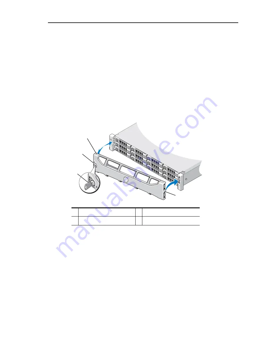
A lock on the bezel restricts access to the power button, and hard drives (

Figure 7

).

Removing the Front Bezel

To remove the front bezel:

1.

Using the appliance key, unlock the bezel.

2.

Lift the release latch next to the key lock.

3.

Rotate the left end of the bezel away from the front panel.

4.

Unhook the right end of the bezel and pull the bezel away from the appliance 
(

Figure 7

).

Figure 7

Removing and Replacing the Front Bezel

Installing the Front Bezel

To install the front bezel:

1.

Hook the right end of the bezel onto the chassis.

2.

Fit the free end of the bezel onto the appliance. 

3.

Secure the bezel with the keylock (

Figure 7

).

1

release latch

2

key lock

3

bezel

4

hinge tabs

4

1

3

2

Содержание 7700 Series

Страница 1: ... Server 7700 M7700 Hardware Guide Release 4 2 2 FCS August 2010 Part Number 010 00863 This manual supports Messaging Operating System MOS release 4 2 2 and later MOS releases until replaced by a newer edition ...

Страница 2: ...ns of this product are Copyright 1997 1998 FreeBSD Inc All Rights Reserved Portions of this product are Copyright 1996 1998 Carnegie Mellon University All Rights Reserved Portions of this product are Copyright 1997 1998 the Apache Group All Rights Reserved Portions of this product are Copyright 1987 2006 Larry Wall All Rights Reserved See http www perl org Portions of this product are Copyright 19...

Страница 3: ...cators 13 Hard Drive Indicator Patterns for RAID 14 Back Panel Features and Indicators 15 Power Indicator Codes 16 Diagnostic Lights 17 NIC Indicator Codes 18 System Messages 19 Warning Messages 19 Diagnostics Messages 19 Alert Messages 19 Other Information You May Need 20 2 Installing Appliance Components 21 Recommended Tools 22 Inside the Appliance 22 Front Bezel 23 Removing the Front Bezel 23 I...

Страница 4: ...s 35 Expansion Card Installation Guidelines 35 Removing an Expansion Card 36 Installing an Expansion Card 37 Removing an Expansion Card Riser 38 Installing an Expansion Card Riser 39 Integrated Storage Controller Card 40 Removing the Integrated Storage Controller Card 40 Installing the Integrated Storage Controller Card 41 Integrated Remote Access Controller 6 iRAC Enterprise Card 42 Removing an i...

Страница 5: ...tions 60 Troubleshooting the Video Subsystem 60 Troubleshooting a USB Device 60 Troubleshooting a Serial I O Device 61 Troubleshooting a NIC 61 Troubleshooting a Wet Appliance 62 Troubleshooting a Damaged System 63 Troubleshooting the System Battery 63 Troubleshooting Power Supplies 64 Troubleshooting System Cooling Problems 64 Troubleshooting a Fan 65 Troubleshooting System Memory 65 Troubleshoot...

Страница 6: ...6 ...

Страница 7: ...out Mirapoint Documentation Documentation for all Mirapoint products is available through the Information Library on the Mirapoint Support website https support mirapoint com The Information Library provides the hardware and software documentation for all supported Mirapoint releases and appliances and the Support Knowledge Base The Support site is accessible to all customers with a valid Support ...

Страница 8: ...nfo Serial number Model Get Serial In the Status tab select System Info Hardware model Model Get Chassis In the Status tab select System Info Table 2 Typographic Conventions in This Manual Typeface Use Example Bold User interface elements From the File menu select Save As Italic Definitions emphasis or titles A folder is a container that stores email messages Specify at least two DNS servers For m...

Страница 9: ...different icons in this manual indicate Table 3 Iconic Conventions in This Manual Icon Use Best practices information Mirapoint recommendations Note information that should be read Critical information License information Potential of causing bodily harm hardware only ...

Страница 10: ...10 Preface ...

Страница 11: ...uring Startup on page 12 Front Panel Features and Indicators on page 13 Hard Drive Indicator Patterns for RAID on page 14 Back Panel Features and Indicators on page 15 Power Indicator Codes on page 16 NIC Indicator Codes on page 18 System Messages on page 19 Warning Messages on page 19 Diagnostics Messages on page 19 Alert Messages on page 19 Other Information You May Need on page 20 ...

Страница 12: ...oint representative Some Unified Server Configurator processing such as software updates can cause virtual devices to be created that at times may appear as USB devices attached to your appliance These connections are both secure and temporary and can be disregarded Ctrl E Enters the iRAC Configuration Utility which allows access to the system event log SEL and configuration of remote access to th...

Страница 13: ...ering on the appliance the video monitor can take from several seconds to over 2 minutes to display an image depending on the amount of memory installed in the appliance CAUTION Never use the power button to power off the appliance 3 NMI button Used to troubleshoot software and device driver errors This button can be pressed using the end of a paper clip CAUTION Use this button only if directed to...

Страница 14: ...atus indicator green and amber 2 drive activity indicator green Drive Status Indicator Pattern RAID Only Condition Blinks green two times per second Identify drive preparing for removal Off Drive ready for insertion or removal NOTE The drive status indicator remains off until all hard drives are initialized after appliance power is applied Drives are not ready for insertion or removal during this ...

Страница 15: ...connectors 2 Embedded 10 100 1000 NIC connectors 7 PCIe expansion card slots using riser card Riser 1 OR Riser 2 Depending on the configuration your appliance may have either riser 1 or riser 2 NOTE for more information refer to the Mirapoint 7 Series Hardware Getting Started Guide that ships with your appliance Connects four PCI Express Generation 2 expansion cards NOTE All four slots are x8 conn...

Страница 16: ...ity of the other installed power supply c When correcting a power supply mismatch replace only the power supply with the flashing indicator Swapping the opposite power supply to make a matched pair can result in an error condition and unexpected appliance shutdown To change from a High Output configuration to an Energy Smart configuration or vice versa you must power off the appliance 9 System sta...

Страница 17: ...Action The appliance is in a normal off condition or a possible pre BIOS failure has occurred The diagnostic lights are not lit after the appliance successfully boots to the operating appliance Plug the appliance into a working electrical outlet and press the power button The appliance is in a normal operating condition after POST Information only BIOS checksum failure detected appliance is in rec...

Страница 18: ...ting Technical Support on page 7 Memory configuration error See Troubleshooting System Memory on page 65 Possible system board resource and or system board hardware failure See Getting Technical Support on page 7 Possible system resource configuration error See Getting Technical Support on page 7 Other failure Ensure that the optical drive and hard drives are properly connected For details about t...

Страница 19: ...ping y yes or n no n Warning messages are generated by either the application or the MOS release For more information see the documentation that accompanied the MOS release Diagnostics Messages The system diagnostic utilities may issue messages if you run diagnostic tests on your appliance Alert Messages Systems management software generates alert messages for your appliance Alert messages include...

Страница 20: ... Guide provides an overview of appliance features setting up your appliance and technical specifications Any media that ships with your appliance that provides documentation and tools for configuring and managing your appliance including those pertaining to the MOS release system management software MOS release updates and appliance components that you purchased with your appliance b Always check ...

Страница 21: ...e Appliance on page 24 Cooling Shroud on page 25 Hard Drives on page 26 Optical Drive on page 28 Cooling Fans on page 28 Power Supplies on page 31 System Memory on page 32 Expansion Cards and Expansion Card Risers on page 35 Integrated Storage Controller Card on page 40 Integrated Remote Access Controller 6 iRAC Enterprise Card on page 42 Processors on page 44 System Battery on page 47 RAID Batter...

Страница 22: ...orized in your product documentation or as directed by the online or telephone service and support team Damage due to servicing that is not authorized by Mirapoint is not covered by your warranty Read and follow the safety instructions that came with the product Figure 6 Inside the Appliance 1 cooling fan 2 internal hard drives 2 3 expansion card riser 4 power supply bays 2 5 cooling shroud 6 heat...

Страница 23: ... Rotate the left end of the bezel away from the front panel 4 Unhook the right end of the bezel and pull the bezel away from the appliance Figure 7 Figure 7 Removing and Replacing the Front Bezel Installing the Front Bezel To install the front bezel 1 Hook the right end of the bezel onto the chassis 2 Fit the free end of the bezel onto the appliance 3 Secure the bezel with the keylock Figure 7 1 r...

Страница 24: ...the appliance and attached peripherals and disconnect the appliance from the electrical outlet and peripherals 2 If installed remove the front bezel Removing the Front Bezel on page 23 3 Rotate the latch release lock on the appliance cover counter clockwise to the unlocked position Figure 8 on page 25 4 Lift up on the latch on top of the appliance and slide the cover back Figure 8 on page 25 5 Gra...

Страница 25: ...h for some time after the appliance has been powered off Allow the memory modules to cool before handling them c Never operate your appliance with the cooling shroud removed Overheating of the appliance can develop quickly resulting in a shutdown of the appliance and the loss of data Removing the Cooling Shroud To remove the cooling shroud 1 Power off the appliance including any attached periphera...

Страница 26: ...e Closing the Appliance on page 24 4 Reconnect the appliance to the electrical outlet and power on the appliance and attached peripherals Hard Drives Your appliance configuration consists of twelve 3 5 inch drive bays All drives are installed at the front of the appliance and connect to the appliance board through the SAS backplane Hard drives are supplied in special hot swappable hard drive carri...

Страница 27: ... Press the button on the front of the drive carrier and open the drive carrier release handle to release the drive Figure 11 on page 28 4 Slide the hard drive out until it is free of the drive bay c To maintain proper appliance cooling all empty hard drive bays must have drive blanks installed 5 Insert a drive blank in the vacated drive bay Installing a Hard Drive Blank on page 27 6 If applicable ...

Страница 28: ...alling the Front Bezel on page 23 Optical Drive An external slimline USB DVD ROM optical drive is provided in the packing box with your appliance In the event of a system recovery this drive is required c Do not lose the external DVD drive Mirapoint recommends keeping this drive stored on top of your appliance Cooling Fans Your appliance contains four dual motor cooling fans These provide cooling ...

Страница 29: ...that came with the product c Do not attempt to operate the appliance without the cooling fans To remove a cooling fan 1 Power off the appliance including any attached peripherals and disconnect the appliance from its electrical outlet 2 Open the appliance Opening the Appliance on page 24 w The cooling fan can continue to spin for some time after the appliance has been powered off Allow time for th...

Страница 30: ...wer the fan into the bracket until the fan is fully seated Figure 12 2 Connect the fan s power cable to the power connector on the system board 3 Route the power cable through the guides on the chassis 4 Close the appliance Closing the Appliance on page 24 5 Reconnect the appliance to the electrical outlet and power the appliance on including any attached peripherals 1 fans 5 2 fan release tab 3 f...

Страница 31: ...er supply bay Removing a Power Supply c If troubleshooting a power supply mismatch error replace only the power supply with the flashing indicator Swapping the opposite power supply to make a matched pair can result in an error condition and unexpected appliance shutdown To change from a High Output configuration to an Energy Smart configuration or vice versa you must power off the appliance To re...

Страница 32: ...rts DDR3 ECC unbuffered DIMMs UDIMMs The appliance contains eight memory sockets split into two sets of four sockets one set per processor Each four socket set is organized into three channels Two DIMMs for channel 0 and a single DIMM for channel 1 and 2 The first socket of each channel is marked with white release levers The maximum memory that is supported on your appliance varies according to t...

Страница 33: ...ertified service technician You should only perform troubleshooting and simple repairs as authorized in your product documentation or as directed by the online or telephone service and support team Damage due to servicing that is not authorized by Mirapoint is not covered by your warranty Read and follow the safety instructions that came with the product w The memory modules are hot to the touch f...

Страница 34: ... module with your thumbs until the ejectors lock into position Figure 14 When the memory module is properly seated in the socket the ejectors on the memory module socket align with the ejectors on the other sockets that have memory modules installed 8 Repeat Steps 5 through 7 of this procedure to install the remaining memory modules Table 5 on page 35 or Table 6 on page 36 9 Replace the cooling sh...

Страница 35: ...regarding the expansion card slots The expansion card slots support full height half length cards The expansion card slots are hot swappable PCI Express Generation 2 expansion cards are supported in all the slots All the slots are x8 connectors c To ensure proper cooling only one of the two expansion cards can have a power consumption of greater than 15 W up to 25 W maximum not including the integ...

Страница 36: ...he electrical outlet 2 Open the appliance Opening the Appliance on page 24 3 Remove the cooling shroud Removing the Cooling Shroud on page 25 4 Disconnect all cables connected to the card 5 Open the expansion card latch Figure 15 on page 37 7 Fibre Channel 2 1 2 Y 8 10 Gb NIC 2 1 2 Y 9 All other NICs 1 2 2 N 10 All other Dell internal storage cards 4 1 Y 11 Non Dell storage cards 1 2 2 N When avai...

Страница 37: ...ance on page 24 9 Reconnect your appliance and peripherals to the electrical outlets and power on the appliance Figure 15 Removing or Installing an Expansion Card Installing an Expansion Card c Many repairs may only be done by a certified service technician You should only perform troubleshooting and simple repairs as authorized in your product documentation or as directed by the online or telepho...

Страница 38: ...position the expansion card so that the card edge connector aligns with the expansion card connector on the expansion card riser 7 Insert the card edge connector firmly into the PCIe card connector until the card is fully seated 8 Close the expansion card latch Figure 15 on page 37 9 Connect any expansion card cables for the new card For information about cable connections refer to the documentati...

Страница 39: ... expansion card riser and lift it from the chassis Figure 16 on page 39 Figure 16 Installing or Removing an Expansion Card Riser Installing an Expansion Card Riser To install an expansion card riser 1 To install an expansion card riser align the riser guides with the riser guide posts on the system board Figure 16 2 Lower the expansion card riser into place until the expansion card riser connector...

Страница 40: ...e by a certified service technician You should only perform troubleshooting and simple repairs as authorized in your product documentation or as directed by the online or telephone service and support team Damage due to servicing that is not authorized by Mirapoint is not covered by your warranty Read and follow the safety instructions that came with the product To remove the integrated storage co...

Страница 41: ...utlet 2 Open the appliance Opening the Appliance on page 24 3 If installed remove the expansion card Removing an Expansion Card on page 36 4 Route the cables in the cable path under the storage controller card slot on the expansion card riser 5 With the storage controller card edge facing the riser insert one side of the card into the black card edge guide 1 storage connector 2 expansion card rise...

Страница 42: ... the appliance Closing the Appliance on page 24 12 Reconnect the appliance to its electrical outlet and power the appliance on including any attached peripherals 13 If applicable replace the front bezel Installing the Front Bezel on page 23 Integrated Remote Access Controller 6 iRAC Enterprise Card The iRAC6 Enterprise card provides a set of advanced features for managing the server remotely Remov...

Страница 43: ...at came with the appliance To install an iRAC6 Enterprise Card 1 Power off the appliance including any attached peripherals and disconnect the appliance from the electrical outlet 2 Open the appliance Opening the Appliance on page 24 3 Remove the plastic filler plug for the iRAC6 Enterprise port from the appliance back panel For the port location see Back Panel Features and Indicators on page 15 4...

Страница 44: ...tative and follow the instructions included in the compressed download file to install the update on your appliance 2 Power off the appliance including any attached peripherals and disconnect the appliance from the electrical outlet 3 Open the appliance Opening the Appliance on page 24 4 Remove the cooling shroud Removing the Cooling Shroud on page 25 w The heat sink and processor are hot to the t...

Страница 45: ...re that the release lever can spring up suddenly if not firmly grasped 9 Position your thumb firmly over the processor socket release lever and release the lever from the locked position Rotate the lever 90 degrees upward until the processor is released from the socket Figure 20 on page 46 Figure 19 Removing and Installing the Heat Sink 10 Rotate the processor shield upward and out of the way Figu...

Страница 46: ...rocessors prior to upgrading your appliance download and install the latest system BIOS version contact your Mirapoint representative Follow the instructions included in the file download to install the update on your appliance 2 Unpack the new processor 3 Align the processor with the socket keys on the ZIF socket Figure 20 c Positioning the processor incorrectly can permanently damage the system ...

Страница 47: ...d on page 26 12 Close the appliance Closing the Appliance on page 24 13 Reconnect your appliance and peripherals to the electrical outlets and power on the appliance 14 Run system diagnostics to verify that the new processor operates correctly System Battery Replacing the System Battery w There is a danger of a new battery exploding if it is incorrectly installed Replace the battery only with the ...

Страница 48: ...tery 8 Support the battery connector by firmly holding the positive side of the connector 9 Press the battery toward the negative side of the connector and lift it up out of the securing tab at the negative side of the connector 10 Support the battery connector by pressing down firmly on the positive side of the connector 11 Hold the new battery with the facing the plastic connector on the system ...

Страница 49: ... product documentation or as directed by the online or telephone service and support team Damage due to servicing that is not authorized by Mirapoint is not covered by your warranty Read and follow the safety instructions that came with the product To remove a RAID battery 1 Power off the appliance including any attached peripherals and disconnect the appliance from the electrical outlet 2 Open th...

Страница 50: ...t team Damage due to servicing that is not authorized by Mirapoint is not covered by your warranty Read and follow the safety instructions that came with the product To remove the control panel module LED 1 If installed remove the front bezel Removing the Front Bezel on page 23 2 Power off the appliance and attached peripherals and disconnect the appliance from the electrical outlet and peripheral...

Страница 51: ...odule Figure 23 3 Connect the control panel cable to the control panel module 4 Replace the bracket and tighten the single screw to secure the bracket to the back of the control panel module 5 Close the appliance Closing the Appliance on page 24 6 Reconnect the appliance to the power source and power on the appliance and attached peripherals 7 If applicable replace the front bezel Installing the F...

Страница 52: ...ppliance on page 24 c To prevent damage to the drives and backplane you must remove the hard drives from the appliance before removing the backplane c You must note the number of each hard drive and temporarily label them before removal so that you can replace them in the same locations 4 Remove all hard drives Removing a Hot Swap Hard Drive on page 27 5 Disconnect the power cable from the end of ...

Страница 53: ...t through the slots in the backplane Figure 24 3 Slide the backplane downward until the two blue retention latches snap into place 4 Connect the SAS data and power cables to the SAS backplane 5 Install the hard drives in their original locations c Handle the cables gently to prevent damage 6 Connect the internal hard drive cables 1 SAS backplane 2 backplane retention latches 2 3 SAS cables 4 contr...

Страница 54: ...ed by Mirapoint is not covered by your warranty Read and follow the safety instructions that came with the product To remove the power distribution board 1 Remove the power supplies from the appliance Removing a Power Supply on page 31 2 Remove the expansion cards Removing an Expansion Card on page 36 3 Remove the expansion card riser Removing an Expansion Card Riser on page 38 4 Disconnect power ...

Страница 55: ...ur warranty Read and follow the safety instructions that came with the product To install the power distribution board 1 Unpack the new power distribution board assembly 2 Align the power distribution board with the tabs on the chassis and slide it in place until the blue tab snaps over the edge of the board Figure 25 3 Install the screws that secure the power distribution board to the chassis Fig...

Страница 56: ...nts inside the appliance Before you begin this procedure review the safety instructions that came with the appliance b After replacing the system board you are required to update the Unified Server Configurator repository to the latest software to restore full functionality Getting Technical Support on page 7 To remove the system board 1 Power off the appliance and attached peripherals and disconn...

Страница 57: ... the labels from the placard and affix them to the information tag on the front of the appliance Figure 1 on page 13 3 Transfer the processors and heat sinks to the new system board Installing a Processor on page 46 4 Remove the memory modules and transfer them to the same locations on the new board System Memory on page 32 5 Install the new system board a Angle the system board as you lower it in...

Страница 58: ...n page 41 8 Install all expansion cards Installing an Expansion Card on page 37 9 Transfer the iRAC6 Enterprise card to the new system board Installing an iRAC6 Enterprise Card on page 43 10 Replace the cooling shroud Installing the Cooling Shroud on page 26 11 Close the appliance Closing the Appliance on page 24 12 Reconnect the appliance and any attached peripherals to the electrical outlet and ...

Страница 59: ...leshooting a Damaged System on page 63 Troubleshooting the System Battery on page 63 Troubleshooting Power Supplies on page 64 Troubleshooting System Cooling Problems on page 64 Troubleshooting a Fan on page 65 Troubleshooting System Memory on page 65 Troubleshooting a Hard Drive on page 67 Troubleshooting a Storage Controller on page 67 Troubleshooting Expansion Cards on page 68 Troubleshooting t...

Страница 60: ...ce disconnect one monitor The appliance supports only one monitor attached to either the front or back video connector 4 Try using a monitor that is known to be working 5 Run the appropriate online diagnostic test If the tests run successfully the problem is not related to video hardware If the tests fail see Getting Technical Support on page 7 Troubleshooting a USB Device To troubleshoot a USB de...

Страница 61: ...d replace the interface cable 3 Power off the appliance and the serial device and swap the device with a comparable device 4 Power on the appliance and the serial device If the problem is resolved replace the serial device If the problem persists see Getting Technical Support on page 7 Troubleshooting a NIC To troubleshoot a NIC 1 Run the appropriate online diagnostic test 2 Restart the appliance ...

Страница 62: ...r off the appliance and attached peripherals and disconnect the appliance from the electrical outlet 2 Open the appliance Opening the Appliance on page 24 3 Disassemble components from the appliance Chapter 2 Installing Appliance Components Cooling shroud Hard drives SD cards NIC hardware key Internal SD Module Expansion cards and both expansion card risers Integrated storage controller iRAC6 Ente...

Страница 63: ...Ensure that the following components are properly installed Expansion cards and both expansion card risers Power supplies Fans and cooling shroud Processors and heat sinks Memory modules Hard drive carriers 4 Ensure that all cables are properly connected 5 Close the appliance Closing the Appliance on page 24 6 Run the system board tests in the system diagnostics If the tests fail see Getting Techn...

Страница 64: ...ondition and unexpected appliance shutdown To change from a High Output configuration to an Energy Smart configuration or vice versa you must power off the appliance 2 Reseat the power supply by removing and reinstalling it Power Supplies on page 31 b After installing a power supply allow several seconds for the appliance to recognize the power supply and to determine if it is working properly The...

Страница 65: ...nly replace one fan at a time 2 Locate the faulty fan indicated by the diagnostic software 3 Reseat the fan Cooling Fans on page 28 b Wait at least 30 seconds for the appliance to recognize the fan and determine whether it is working properly 4 If the problem is not resolved install a new fan If the replacement fan does not operate see Getting Technical Support on page 7 Troubleshooting System Mem...

Страница 66: ...onnect the appliance to its electrical outlet and power on the appliance and attached peripherals If the problem is not resolved proceed with the next step 12 Power off the appliance and attached peripherals and disconnect the appliance from the power source 13 Open the appliance Opening the Appliance on page 24 14 Remove the cooling shroud Removing the Cooling Shroud on page 25 15 If a diagnostic...

Страница 67: ...apter for information about the configuration utility b Ensure that the hard drive s have been configured correctly for the RAID array c Take the hard drive offline and then reseat the hard drive Removing a Hot Swap Hard Drive on page 27 d Exit the configuration utility and allow the appliance to boot to the operating system 4 Ensure that the required device drivers for your controller card are in...

Страница 68: ...eated 9 Verify that the cable connections between the SAS backplane and the integrated storage controller are correct Installing the Integrated Storage Controller Card on page 41 10 Ensure that the cables are firmly connected to the storage controller and the SAS backplane board 11 Close the appliance Closing the Appliance on page 24 12 Reconnect the appliance to its electrical outlet and power on...

Страница 69: ...4 14 Reconnect the appliance to the electrical outlet and power on the appliance and attached peripherals 15 Run the appropriate online diagnostic test If the tests fail see Getting Technical Support on page 7 16 For each expansion card you removed in Step 11 perform the following steps a Power off the appliance and attached peripherals and disconnect the appliance from the electrical outlet b Ope...

Страница 70: ...r Bending the pins can permanently damage the system board 13 Remove processor 2 Removing a Processor on page 44 14 Replace the cooling shroud Installing the Cooling Shroud on page 26 15 Close the appliance Closing the Appliance on page 24 16 Reconnect the appliance to the electrical outlet and power on the appliance and attached peripherals 17 Run the appropriate online diagnostic test If the tes...

Страница 71: ...ws the location of the configuration jumpers on the system board Table 7 lists the jumper settings Table 7 System Board Jumper Settings Jumper Setting Description PWRD_EN default The password feature is enabled pins 2 4 The password feature is disabled and iRAC6 local access is unlocked at the next AC power cycle pins 4 6 NVRAM_CLR default The configuration settings are retained at system boot pin...

Страница 72: ... Connectors Item Connector Description 1 CPU2 Processor 2 2 iRAC6 Enterprise iRAC6 Enterprise card connector 3 B4 B1 B2 B3 Memory module slot B4 Memory module slot B1 white release lever Memory module slot B2 white release lever Memory module slot B3 white release lever 4 CPU1 Processor 1 5 FAN1 Cooling fan 1 connector 6 FAN2 Cooling fan 2 connector 3 4 14 16 15 1 2 5 6 7 8 1 1 12 13 17 18 19 20 9...

Страница 73: ...he appliance including any attached peripherals and disconnect the appliance from the electrical outlet 7 A3 A2 A1 A4 Memory module slot A3 white release lever Memory module slot A2 white release lever Memory module slot A1 white release lever Memory module slot A4 8 FAN3 Cooling fan 3 connector 9 BATTERY System battery 10 FAN4 Cooling fan 4 connector 11 12V 8 pin power connector 12 FP_CONN contro...

Страница 74: ... assign a new system and or setup password you must return the jumper plug to the enabled position n If you assign a new system and or setup password with the jumper plug still in the disabled position the system disables the new password s the next time it boots 6 Power off the appliance including any attached peripherals and disconnect the appliance from the electrical outlet 7 Open the applianc...

Страница 75: ...e Your rights under this License will terminate automatically without notice from Mirapoint if you fail to comply with any term s of this License User acknowledges and agrees that any unauthorized use transfer sublicensing or disclosure of the Mirapoint Software may cause irreparable injury to Mirapoint and under such circumstances Mirapoint shall be entitled to equitable relief without posting bo...

Страница 76: ...tment s Bureau of Industry and Security which include the name and address including country of each transferee and f understands that countries including the United States may restrict the import use or export of encryption products which may include the Mirapoint Software and the components and agrees that it shall be solely responsible for compliance with any such import use or export restricti...

Отзывы: