background image

17

 © 2015 Minuteman International, Inc.

X17 ECO CFS Carpet Extractor  #988751UM  Rev. *  04/15

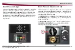
Brush Pressure Gauge

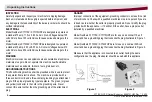
The brush pressure gauge informs the operator if the brush 

pressure setting is in optimum range. (See Figure 3) The 

machine operates best in the green range. If the machine 

reaches the yellow or red range, the brush pressure can 

be lowered by using the Brush Pressure Adjustment Knob.  

See Brush Pressure Adjustment Knob for brush pressure 

adjustments.

Machine Overview

Figure 3

Figure 4

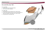
Brush Pressure Adjustment Knob

The Brush Pressure Adjustment Knob allows the operator to 

decrease or increase the brush pressure.  The adjustment 

knob (item A, Figure 4) is located on the lower right side of 

the back panel of the machine.
To 

DECREASE

 brush pressure: Turn the adjustment knob 

CLOCKWISE

 (in the ‘-’ direction) until the desired pressure 

range is achieved.
To 

INCREASE

 brush pressure: Turn the adjustment knob 

COUNTER-CLOCKWISE

 (in the ‘+’ direction) until the 

desired pressure range is achieved.

Содержание X17

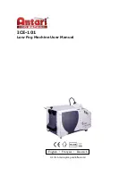
Страница 1: ...User Manual X17 ECO CFS Carpet Extractor 115V 230V with High Pressure Minuteman Minuteman International Inc A Member of the Hako Group 988751UM Rev 04 15 ...

Страница 2: ...tors must read and understand this manual before operating or servicing this machine This machine was designed to give you excellent performance and efficiency For best results and minimal cost please follow the general guidelines below Operate the machine with reasonable care Follow the manufacturer s suggested maintenance instructions as provided in this booklet Use original Minuteman supplied p...

Страница 3: ...5 LITERS 7 Gallon 26 5 LITERS Power Cord Length 50 ft 15 24m 50 ft 15 24m Suction sealed 100in of water 100in of water Vibration 8 2 ft s2 2 5 m s2 Noise emission The sound pressure level measured under maximum conditions 83 dB A of use LwA according to DIN EN 60335 2 68 The sound pressure level measured at the ear of the driver under 72 dB A normal conditions of use LpA according to DIN EN 60335 ...

Страница 4: ... Front 10 Vacuum Connection 10 X17 CFS Back Bottom 11 Handle Control Panel 12 Circuit Breakers 13 CFS Control Box 13 Solution Tank In line Filter 14 Vacuum Intake Filter 14 Solution Tank Drain Hose 15 Solution Level Indicator 15 Brush Removal 16 Brush Pressure Gauge 17 Brush Pressure Adjustment Knob 17 Removable Recovery Tank 18 Handle Adjustment 19 Cord Relief 19 Accessories 20 Maintenance 21 Ope...

Страница 5: ...turn it to a service center Do not pull or carry by cord use cord as a handle close a door on cord or pull cord around sharp edges or corners Do not run appliance over cord Keep cord away from heated surfaces Do not unplug by pulling on cord To unplug grasp the plug not the cord Do not handle plug or appliance with wet hands Do not put any object into openings Do not use with any opening blocked k...

Страница 6: ...e to protect the operator from electric shock The machine is provided with a three conductor cord and a three contact grounding type attachment plug to fit the proper grounding type receptacle The green or green and yellow conductor in the cord is the grounding wire Never connect this wire to other than the grounding pin of the attachment plug DANGER Improper connection of the equipment grounding ...

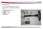
Страница 7: ... C B E D F Handle Assembly The X17 CFS Handle Assembly D is not assembled on the machine when shipped Follow the instruction on the next page to connect the handle assembly to the machine A HANDLE ADJUSTMENT KNOB B SHOULDER BOLT C COVER D HANDLE ASSEMBLY E SCREW F CORD RELIEF Assembly ...

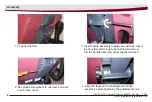
Страница 8: ...iver to unscrew 4 screws and remove cover 3 Insert handle assembly in between bushings Insert the shoulder bolt through the bushing and screw into the handle assembly using supplied wrench 4 Align the teeth on the bushing and handle assembly before tightening the adjustment knob 1 Unpack machine Assembly ...

Страница 9: ...arpet Extractor 988751UM Rev 04 15 Assembly 6 Attach the wire harness to the machine 7 The wire harness must be aligned with the patterns on the connector to fit 8 Screw the cover back with the 4 screws 5 Spin the adjustment knobclockwise to tighten ...

Страница 10: ...ction K VACUUM MOTOR INTAKE COVER L VACUUM CONNECTION TUBE M RECOVERY INLET N RECOVERY TANK HANDLE P VACUUM FLOAT SHUT OFF Q RECOVERY WINDOW EXTENSION HOSE R VACUUM MOTOR GASKET X17 CFS Front A HANDLE B RECOVERY DOME LID C RECOVERY TANK D SOLUTION TANK E SOLUTION TANK FILL PORT F FAUCET FILL HOSE G RECOVERY WINDOW H BRUSH MOTOR BELT COVER J VAC SHOE ...

Страница 11: ...OB C AUXILIARY POWER OUTLET FOR MINUTEMAN MOTORIZED TOOL ONLY D RECOVERY TANK DUMP HOSE E BRUSH PRESSURE ADJUSTMENT KNOB F OFF AISLE WAND WATER FEMALE QUICK CONNECT G VACUUM HOSE CONNECTION POINT H IN LINE SOLUTION FILTER J VAC SHOE K BRUSH L BRUSH END COVER M SPRAY JETS 2 N BRUSH MOTOR P SOLUTION TANK DRAIN HOSE R CFS CONTROL BOX ON OFF Machine Overview ...

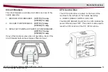
Страница 12: ...tion to shut OFF vacuum D Spray Jet Auxiliary Switch Off Aisle Wand 3 Position switch for spray jet and auxiliary mode function 0 position is a neutral OFF position In the 0 postion the Spray Jet and Auxiliary Mode are OFF Press switch up to I position to turn ON the spray jets Press switch down to II position to turn ON Auxiliary Mode Off Aisle Wand OAW This will power the auxiliary outlet and tu...

Страница 13: ...7 5 amp 3 SPRAY JET PUMP AUX POWER PUMP BREAKER X17115 1 5 amp X17230 1 0 amp If any of the functions above are not operating check if the circuit breaker buttons have tripped Press to reset 2 3 1 3 1 CFS Control Box The CFS Control Box is located on the back of the machine to the left side of the handle assembly A ON OFF RESET SWITCH FOR CFS The ON OFF RESET Switch for the CFS controls the power ...

Страница 14: ...y hand Note Using tools to tighten may damage plastic threads 5 Open the Shut off Valve C by turning the handle 90O counterclockwise Vacuum Intake Filter The Vacuum Intake Filter protects the intake vacuum from large debris This filter should be cleaned regularly Steps to cleaning Vacuum Intake Filter 1 Unplug machine from power source outlet 2 Drain Solution and Recovery tanks 3 Filter is located...

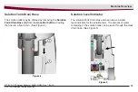
Страница 15: ...he Solution Tank Drain Hose A from the Hose Barb B and routing the hose to a floor drain See Figure 4 Solution Level Indicator The solution Tank Drain Hose also serves as a water level indicator for the solution tank The amount of water remaining in the solution tank can be seen through the clear drain hose See Figure 5 Machine Overview Figure 4 Figure 5 ...

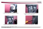
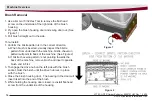
Страница 16: ...n a When brush is inserted visually inspect the bristle pattern from underneath the machine bristle cheveron pattern will point to back of the machine See Figure 2 b If bristle cheveron pattern is not pointing towards the back of the machine remove brush and insert opposite brush end in first 3 To engage the drive hub on the left side with the brush socket twist the brush until the drive hub lock ...

Страница 17: ...e Brush Pressure Adjustment Knob for brush pressure adjustments Machine Overview Figure 3 Figure 4 Brush Pressure Adjustment Knob The Brush Pressure Adjustment Knob allows the operator to decrease or increase the brush pressure The adjustment knob item A Figure 4 is located on the lower right side of the back panel of the machine To DECREASE brush pressure Turn the adjustment knob CLOCKWISE in the...

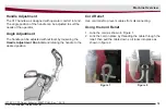
Страница 18: ...vable Recovery Tank To remove tank 1 Unclip dump hose from solution tank 2 Pull recovery tank straight up To replace tank 1 Feed dump hose through opening in solution tank 2 Lower tank into place Recovery vacuum inlet will rest on vacuum connection tube See pg 10 items L M 3 Clip dump hose to solution tank ...

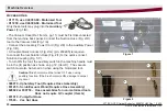
Страница 19: ... Angle Adjustment The handle can be adjusted without tools by loosening the Handle Adjustment Knob A and rotating the handle to the desired position Machine Overview Cord Relief Use cord relief to prevent cables from disconnecting Using the Cord Relief 1 Loop the cord as shown in Figure 1 2 Lock the cord in place by threading the cable through the relief then pull the cable down so it locks into p...

Страница 20: ...tem G pg 11 must be first disconnected from the machine back panel Connect the Suction Hose Fig 2 D tool to the Vacuum Inlet Fig 1 A Connect the accessory Power Cord Fig 2 E to the Auxiliary Power Fig 1 B A Coupler Quick Connect Fig 2 G p n 450295 is required to connect the tool Solution Hose Fig 2 F to the quick connect Solution Coupling Fig 1 C To turn ON the tool the auxiliary switch in the mac...

Страница 21: ...n level drain hose Both require flushing for best performance 2 Removable recovery tank should be rinsed clean and drained using dump hose Tank does not need to be removed Wipe off any debris from O ring under dump hose cap 3 Dome lid should be cleaned Pull or rinse off any debris from the attached Filter Place lid upside down when storing machine for ventilation to prevent odor build up 4 Vacuum ...

Страница 22: ...ends 3 Wipe off any debris from bottom side of chassis 4 Rinse off the Dome Lid Filter Maintenance Monthly 1 Check Spray Jets for full width spray pattern Remove twist orange cap turn counter clockwise and clean with soft bristle brush if necessary Do not use pins or wire which can damage the spray tip 2 Clean the Recovery Window pg 10 item G by removing 2 screws and wiping out with a soft cloth u...

Страница 23: ... plug If appliance is not working as it should has been dropped damaged left outdoors or dropped into water return to service center Do not pull or carry by cord use cord as handle close a door on cord or pull cord around sharp edges or corners Do not run appliance over cord Keep cord away from heated surfaces Do not unplug by pulling cord To unplug grasp the plug not the cord Do not handle plug o...

Страница 24: ...g rubber inlet against faucet 2 Fill solution tank with desired amount of warm water MAX water temperature is 120 F 50 C Ref C See Decal 17262197 below DO NOT add Chemicals or Detergents WATER ONLY when filling the X17 CFS solution tank Ref A See Decal 715474 below Adding chemicals or detergents will prematurely reduce the life of the CFS system Decal 17262197 Operating Instructions Operating Inst...

Страница 25: ...ig 1 D spray jet to the center position O 6 before the end of each cleaning pass During the cleaning cycle care should be taken not to allow foam to build up in the recovery tank If this should happen the machine should be turned off Defoamer order 910543 should be added to the recovery tank only never into the solution tank Foam should not be seen inside the right side of the dome lid The recover...

Страница 26: ...osed Open valve Sprayjet Switch is in OFF O or AUX II position Flip sprayjet switch to ON I position No water in solution tank Fill solution tank Spray intermittent or streaked Solution hoses may be clogged or kinked Check hose for clogs remove any debris if found Replace kinked hose if found Solution tank in line filter valve may be clogged Clean strainer thoroughly The spray jets may be clogged ...

Страница 27: ...covery tank is not seated properly over intake tube Reposition recovery tank so the intake tube is inserted into the inlet Recovery tank dump hose may not be closed properly Disconnect cap from drain hose then reconnect to ensure the cap and hose snap together Bad seals on recovery dome lid Check the gasket on the lid for damage Replace if needed Vac shoe may be clogged Check vac shoe for debris a...

Страница 28: ... potential health hazard exists without original equipment replacement All warranted items become the sole property of Minuteman or its original manufacturer whichever the case may be Minuteman disclaims any implied warranty including the warranty of merchantability and the warranty of fitness for a particular purpose Minuteman assumes no responsibility for any special incidental or consequential ...

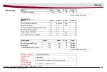
Страница 29: ...tor Upright Vacuums 1yr 1yr 0 0 Explosion Proof Vacuum 1yr 1yr 0 0 CBox HBox TRS 14 1yr 1yr 10yrs 0 E17 E20 Electric Scrubbers 3yr 2yr 10yrs 0 Description Parts Labor Poly Travel Battery Operated Group 3yrs 2yrs 10 90 days Sweepers 1yr 1yr 0 90 days Internal Combustion Group 1yr 1yr 0 90 days Not to exceed two hours Battery Chargers One year replacement Replacement Parts Ninety days Batteries 0 3 ...

Страница 30: ...Excellence Meets Clean Minuteman International Inc 14N845 U S Route 20 Pingree Grove Illinois 60140 USA Phone 800 323 9420 www minutemanintl com A Member of the Hako Group 988751UM Rev 04 15 ...

Отзывы: