background image

8-40

Network Interface Card (NIC)

Ins

tal

ling O

p

tio

n

s

Cha

p

ter 8

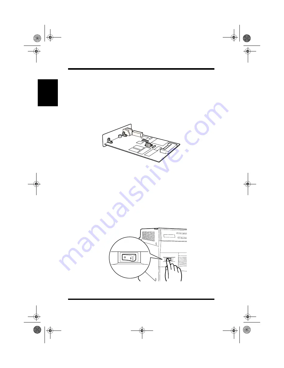
Network Interface Card (NIC)

There are two optional network interface cards that are supported by 
this printer: 

10/100Base-T 

and 

10BaseT/2

. The NIC option that you 

select should be determined according to the requirements of your 
network environment. For details, see the Network Interface Card 
User’s Manual.

* This illustration shows the optional 10/100Base-T Network Interface 

Card.

Installing the optional network interface card

1

Turn the printer off and unplug the power cord from the printer. 
Disconnect the cable from the interface connector.

25pw.book  Page 40  Thursday, March 16, 2000  10:29 AM

Содержание PageWorks 25

Страница 1: ...PageWorks 25 User s Manual...

Страница 2: ......

Страница 3: ...s for energy efficiency What is an ENERGY STAR Printer ENERGY STAR Printers have a feature that allows them to automatically go to sleep after a period of inactivity This auto feature can reduce a mac...

Страница 4: ...Internal Laser Radiation Maximum Average Radiant Power 36 7 W at laser aperture of the print head unit Wavelength 770 810 nm This product employs Class IIIb Laser Diode that has an invisible laser bea...

Страница 5: ...the U S Department of Health and Human Services DHHS This means that the product does not produce haz ardous laser radiation The label shown below indicates compliance with the CDRH regulations and mu...

Страница 6: ...4179 251 4179 241 Adobe PostScript SIMM 4179 411 Hard Disk Drive 2 1GB 4179 301 Tested To Comply With FCC Standards FOR HOME OR OFFICE USE This device complies with Part 15 of the FCC Rules Operation...

Страница 7: ...or more of the fol lowing measures Re orient or relocate the receiving antenna Increase the separation between the equipment and the receiver Connect the equipment to an outlet on a circuit different...

Страница 8: ...ugh to harm anyone adversely However be sure the room where the printer is being used has adequate ventilation especially if you are print ing a high volume of materials or if the machine is being use...

Страница 9: ...rieval system or translated into other languages without the express written prior consent of Minolta Co Ltd The contents of this manual are subject to change without notice Trademark Acknowledgments...

Страница 10: ...technical assistance at http www minoltaprinters com Please be prepared to provide the following information when contacting Minolta Technical Support Model Name Serial number A detailed description...

Страница 11: ...Control Panel 1 6 Layout for Control Panel 1 6 Indicator Lights 1 7 The LCD Display Panel 1 7 Key Functions 1 8 On Line key 1 8 Proceed key 1 8 Tray1 Paper key 1 8 Shift key 1 8 Menu key 1 8 Item key...

Страница 12: ...2 3 Operational Precautions 2 5 Operating Environment 2 5 Printer 2 5 Printer Supplies 2 8 Moving the Printer 2 9 Setting Up 2 10 Installing the Imaging Cartridge 2 10 Connecting the Power Cord 2 14 T...

Страница 13: ...arallel Menu 3 14 Network Menu 3 15 Maintenance Menu 3 17 Adjust Menu 3 19 Test Print Menu 3 21 Printing Paper 3 22 Type 3 22 Size 3 23 Loading Paper 3 26 Loading Paper onto Tray 1 3 26 Loading Paper...

Страница 14: ...djusting the top margin 3 54 Adjusting the left margin 3 58 Adjusting the left margin for duplex printing 3 62 Chapter 4 Printer Driver Introduction 4 1 System Requirements 4 1 Installing the PageWork...

Страница 15: ...ialog under Windows 95 98 4 17 To display the PageWorks 25 driver setup dialog under Windows NT 4 0 4 19 Using PageWorks 25 Printer Driver Setup Dialog 4 21 Common Buttons 4 21 Paper 4 22 Page Layout...

Страница 16: ...ing the Printer 6 8 Cleaning the Outside of the Printer 6 8 Cleaning the Paper Feed Roller 6 9 Replacing the Maintenance Kit 6 11 Replacing the Image Transfer Roller Unit 6 11 To reset the counter of...

Страница 17: ...the Duplex Unit 7 7 Paper Output Misfeed Output Tray 7 7 Paper Output Misfeed 5 bin Mail bin 7 9 Paper Output Misfeed 10 bin Mail bin 7 10 METHOD 1 main unit 7 10 METHOD 2 horizontal transport unit 7...

Страница 18: ...7 Standard Status Messages 7 27 Caution Messages 7 29 Auto Continuable Messages 7 30 Operator Call Messages 7 31 Service man Call Messages 7 37 Chapter 8 Installing Options Installing the Duplex Kit 8...

Страница 19: ...k Interface Card NIC 8 40 Installing the optional network interface card 8 40 PostScript ROM SIMM 8 44 Installing the optional PostScript ROM SIMM 8 44 Hard Disk Drive 8 48 Installing the optional Har...

Страница 20: ...xvii Contents 5 bin Mail bin Option 9 8 10 bin Mail bin Option 9 9 SIMM Option 9 10 Appendix A Glossary Appendix B Index 25pw book Page xvii Thursday March 16 2000 10 29 AM...

Страница 21: ...MEMO 25pw book Page xviii Thursday March 16 2000 10 29 AM...

Страница 22: ...Chapter Introduction 1 Introduction Chapter 1 25pw book Page 1 Thursday March 16 2000 10 29 AM...

Страница 23: ...Introduction Chapter 1 25pw book Page 0 Thursday March 16 2000 10 29 AM...

Страница 24: ...the PageWorks 25 to transfer data at remarkably high speeds An 8MB memory is standard with the option of enlarging up to a maximum of 104MB As a result you can utilize high speed processing of large v...

Страница 25: ...itionally you have the option of either a 5 or 10 bin Mail bin for greater flexibility with your output options There s even a duplexing function for double sided output Large Volume Paper Trays A lar...

Страница 26: ...Accessories Tray 2 Control Power Side cover Side cover Paper size selection dial Parallel interface Power cord Tray 1 switch panel release lever multipurpose tray 500 sheet tray connector socket Tray...

Страница 27: ...Printer Parts and Accessories 1 4 Introduction Chapter 1 Image transfer roller Paper guide Paper feed roller Imaging cartridge Fusing unit 25pw book Page 4 Thursday March 16 2000 10 29 AM...

Страница 28: ...pter 1 5 bin Mail bin Upper attachment Horizontal transport unit Printer Manual feed unit Tray 3 4 5 250 sheet paper feed unit 500 sheet paper feed unit 2500 Sheet 10 bin Mail bin Tray LCC Duplex unit...

Страница 29: ...e control panel consists of a display panel LCD three indicator lights and eight function keys 1 Data indicator 7 Shift key 2 Message indicator 8 Enter Job Cancel key 3 On Line indicator 9 Select key...

Страница 30: ...This line is blank under normal conditions Note Indicator On Off blinking DATA Data is being stored in the printer memory No data is stored in the printer memory The printer is receiving data and proc...

Страница 31: ...ode You can only enter this mode when the printer is off line The TRAY1 PAPER SIZE menu is only displayed when the Tray 1 paper size selection dial is set to User Set see page 3 30 Shift key The shift...

Страница 32: ...y can be pressed in combination with the Shift key to cancel a job that is currently being processed and to clear the data for a job from the printer s memory A job can only be cancelled by using the...

Страница 33: ...MEMO Introduction Chapter 1 25pw book Page 10 Thursday March 16 2000 10 29 AM...

Страница 34: ...Chapter Setting Up 2 Setting Up Chapter 2 25pw book Page 1 Thursday March 16 2000 10 29 AM...

Страница 35: ...Setting Up Chapter 2 25pw book Page 0 Thursday March 16 2000 10 29 AM...

Страница 36: ...eing generated in the area The power outlet you plan to connect to for power should be nearby and unobstructed Make sure that the printer is not exposed to direct sunlight Avoid areas in the direct ai...

Страница 37: ...is printer Be sure to plug the power cord all the way into the outlet The outlet should be located near the printer and easily accessible so you can unplug the power cord immediately should any proble...

Страница 38: ...sure to provide space around the printer as indicated below to ensure easier printer operation paper and toner replacement and maintenance Standard 100 mm 300 mm 600 mm 4 940 mm 37 11 3 4 300 mm 11 3...

Страница 39: ...h Optional Paper Feed Units 10 bin Mail bin and Duplex Kit 1200 mm 47 1 4 300 mm 11 3 4 200 mm 7 3 4 1140 mm 45 400 mm 15 3 4 600 mm 23 1 2 1450 mm 57 1200 mm 47 1 4 300 mm 11 3 4 900 mm 35 1 2 400 mm...

Страница 40: ...open any of its covers during a print operation Never locate any object that generates magnetic force flammable gas or flammable liquid near the printer When unplugging the power cord always grasp the...

Страница 41: ...es or other small pieces of metal do not get into the printer through its vents or other open ings Such objects create the danger of fire or electrical shock Do not allow water or other liquids to spi...

Страница 42: ...of ozone is generated during normal operation of this printer Because of this an unpleasant odor may result when the printer is used for extensive printing in a poorly ventilated area For comfortable...

Страница 43: ...midity Areas subjected to large amounts of dust Keep paper that has been removed from its wrapper but not yet loaded onto the printer tray in a sealed plastic bag and store it in a cool dark location...

Страница 44: ...ing to move the printer remove the imaging cartridge Protect the imaging cartridge from exposure to light by covering it with a cloth whenever it is removed from the printer Remove any options that ma...

Страница 45: ...nter before unpacking Set up the printer according to the following instructions Note Installing the Imaging Cartridge 1 Pull the side cover release lever and open the side cover Keep all the boxes an...

Страница 46: ...ht forward and back 3 Carefully remove the packing tape that is adhered to the grips by pulling from the bottom up Never touch the copper and brass electrode that is located inside the side cover and...

Страница 47: ...green guides on the imaging cartridge with the slot bearing the green seal located inside of the printer Insert the imaging cartridge as far as it will go inside of the printer 5 Close the side cover...

Страница 48: ...ake sure that the side cover is closed correctly If it is difficult to close the side cover push the green tabs of the imaging cartridge as far as they will go inside the printer and try again 25pw bo...

Страница 49: ...wer Cord 1 Make sure that the printer s power switch is in the Off posi tion 2 Connect one end of the power cord that comes with the printer to the power cord socket Plug the other end into a power ou...

Страница 50: ...aving mode after a preset period of time in which it does not receive a print command from the computer The time period can be preset through the control panel see page 3 9 The printer requires approx...

Страница 51: ...2 Make sure that READY appears in the message display indicat ing that there is no existing error condition and that there is cur rently no data in the printer s memory 3 Press the On Line key to tak...

Страница 52: ...to print or if an error message should appear on the message display while printing the Test Page It is only possible to print the test page on Letter sized paper The test page is printed according to...

Страница 53: ...le to the parallel interface con nector on the back of the printer Secure the cable using the two clips on the parallel interface connector See page 9 3 of this User s Manual for cable specifications...

Страница 54: ...Chapter Using the Printer 3 Using the Printer Chapter 3 25pw book Page 1 Thursday March 16 2000 10 29 AM...

Страница 55: ...Using the Printer Chapter 3 25pw book Page 0 Thursday March 16 2000 10 29 AM...

Страница 56: ...It is not possible to change a setting through the driver You make printer configuration settings that are not a part of the driver You need to identify the fonts that are stored in your printer s me...

Страница 57: ...ry to change the user selection You can return to the menu mode by pressing the Menu key You can return to the item mode by pressing the Item key 5 Press the Enter key to save your selection An asteri...

Страница 58: ...e that the dial located on the front side of Tray 1 is set to a position other than User Set 2 TRAY1 PAPER SIZE is displayed only when the dial located on the front side of Tray 1 is set to User Set N...

Страница 59: ...ome items and values are only used with a particular printer language All of the items and values on these menus can be selected however they will only take effect if the appropriate printer language...

Страница 60: ...tem Factory Default User Selection COPIES 1 1 to 999 PAPER SIZE LETTER LETTER LEDGER JIS B5 LEGAL EXECUTIVE A3 JIS B4 A4 A5 PAPER SOURCE AUTO AUTO TRAY1 TRAY2 TRAY3 TRAY4 TRAY5 LCC MANUAL FEED ORIENTA...

Страница 61: ...e page is wider than it is tall when you view the printed text upright DUPLEX Allows you to print two pages at one time using the front and back of a sheet of paper The two sided document can be print...

Страница 62: ...ITCH 10 00 0 44 99 99 POINT 12 4 00 999 75 SYMBOL SET ROMAN 8 ROMAN 8 ISO LATIN1 ISO LATIN2 ISO LATIN5 ISO LATIN 6 PC 775 PC 8 PC 8 D N PC 850 PC 852 PC 866 PC TURKISH PC 1004 WIN3 1 LATIN1 WIN3 1 LAT...

Страница 63: ...er Print the font list from the Test Print Menu see page 3 21 to learn the number of a specific font PITCH Pitch refers to the number of characters that can be printed per hori zontal inch This settin...

Страница 64: ...SAVE 45 0 120 AUTO CONTINUE OFF OFF 20 SEC 30 SEC 60 SEC 90 SEC 120 SEC PAPER TIMEOUT OFF OFF PROCEED JOB CANCEL JOB PRIORITY SOURCE TRAY 2 TRAY1 TRAY2 TRAY3 TRAY4 TRAY5 LCC CASSETTE LOCK NONE NONE T...

Страница 65: ...cally reprint a misfed page in the PCL mode when PCL Jam Recovery is set to Off PS JAM RECOVERY When this setting is enabled On documents are saved in the printer s memory until they have been output...

Страница 66: ...or or Caution alert is detected See Auto Continuable Message on page 7 30 PAPER TIMEOUT This setting specifies whether the printer will automatically recover whenever paper size mismatch error or manu...

Страница 67: ...rd disk and an increased amount of RAM The RAM option requires an additional amount of RAM only If these requirements for Context Save are not supplied this menu will not appear The default setting fo...

Страница 68: ...e purpose of any optional mail bins that may installed Bins that are not selected here will be used as the stacker and separator bins The same settings that are entered here should also be entered in...

Страница 69: ...at was sent from the computer The IO Time out setting acts as a timer that allows the printer a specified period of time in which to determine if a document has finished printing or not If an IO Timeo...

Страница 70: ...e value of each field of an IP address must be a number from 0 to 255 Item Factory Default User Selection TCP IP RECEIVE ON RECEIVE ON RECEIVE OFF IP ADDRESS XXX XXX XXX XXX SUBNET MASK XXX XXX XXX XX...

Страница 71: ...ON this setting allows for the transfer of data via Apple Talk IO TIMEOUT An IO Timeout occurs when the printer cannot detect the final data code for a print job that was sent from the network interfa...

Страница 72: ...arge Size Count Item Factory Default User Selection DISPLAY LANGUAGE ENGLISH ENGLISH DEUTSCH FRANCAIS ITALIANO NEDERLANDS DANSK ESPA OL CESTINA FACTORY DEFAULT HARD DRIVE DISK FORMAT FORMAT OK TRANSFE...

Страница 73: ...d go into the READY mode DISK FORMAT is only dis played when the optional hard disk drive is installed TRANSFER LIFE This setting is used to reset the counter for the image transfer roller Note 100 RE...

Страница 74: ...1 LEFTOFFSET This setting specifies the horizontal value for Image Shift when doc uments are generated using Tray 1 Item Factory Default User Selection TONER DENSITY MEDIUM EXTRA LIGHT LIGHT MEDIUM LI...

Страница 75: ...t when doc uments are generated using Tray 4 TRAY5 LEFTOFFSET This setting specifies the horizontal value for Image Shift when doc uments are generated using Tray 5 LCC LEFTOFFSET This setting specifi...

Страница 76: ...ol panel printer information and installed options See page 2 17 for a sample test page PCL FONT LIST Prints a page containing the font list for the PCL configuration PS FONT LIST Prints a page contai...

Страница 77: ...al 250 500 sheet paper feed unit Optional 2500 sheet tray Plain Paper weighing 60 to 90 g m2 16 to 24 lbs Recycled Paper weighing 60 to 90 g m2 16 to 24 lbs Special Paper Transparency Sheet None None...

Страница 78: ...Tray 1 Tray 2 Optional manual feed unit Optional 250 sheet paper feed unit Optional 500 sheet paper feed unit Optional 2500 sheet tray Standard Size A4 210 297 mm 1 None A3 297 420 mm None 2 None A5 1...

Страница 79: ...one None None None Env Monarch 3 7 8 7 1 2 None None None None Custom 92 to 297 140 to 432 mm 3 1 2 to 11 3 4 5 1 2 to 17 None None None None Do not use the following types of paper to avoid reduced p...

Страница 80: ...e glued portion Those having flaps the full width of the envelope unacceptable if the flap is glued Wrinkle free no fasteners Generally envelopes perform well but some types may wrinkle We strongly re...

Страница 81: ...ge Keep paper out of areas that are subject to extreme temperatures or humidity Loading Paper onto Tray 1 Tray 1 is designed to hold up to 250 sheets of plain recycled paper and support the following...

Страница 82: ...Loading Paper Using the Printer Chapter 3 1 Slide open Tray 1 2 Press down on the paper lifting plate located inside of Tray 1 until it clicks into place 25pw book Page 27 Thursday March 16 2000 10 2...

Страница 83: ...the green clip to the appropriate paper size by squeezing its sides and sliding it through the runner at the bottom of the tray 4 Press the green button located near the outer edge of the tray to adju...

Страница 84: ...er lengthwise into the tray so that the short edge of the paper faces the outer edge of the tray Place custom size paper and envelopes widthwise into the tray Envelopes should be placed so that the fl...

Страница 85: ...r size set the media type for Tray 1 through the Tray 1 Paper Mode on the control panel see page 3 3 When printing on envelopes and custom sized paper it is neces sary to set the dial to User Set and...

Страница 86: ...ray 2 Tray 2 is designed to hold up to 500 sheets of the following paper sizes A4 Legal Letter Executive 1 Slide open Tray 2 2 Press down on the paper lifting plate located inside of Tray 2 until it c...

Страница 87: ...ng to step 4 4 Load the proper size of paper within the braces The stack of paper that is loaded onto the tray should not exceed the maximum level indicator see illustration Note Place paper of Letter...

Страница 88: ...3 33 Loading Paper Using the Printer Chapter 3 5 Set the size of paper loaded in the tray on the dial 6 Close Tray 2 25pw book Page 33 Thursday March 16 2000 10 29 AM...

Страница 89: ...ge of 500 sheet paper feed units that support different paper sizes The 500 sheet paper feed unit options are designed to hold up to 500 sheets of paper respectively of the following paper sizes 1 Sli...

Страница 90: ...it clicks into place 3 If necessary adjust the paper braces to the size of the paper to be loaded Use a phillip s head screwdriver to remove the braces from the tray Be sure to secure the braces into...

Страница 91: ...the maximum level indicator see illustration Note 5 Set the size of paper loaded in the tray on the dial 6 Close the tray Place A4 Letter and Executive size paper lengthwise into the tray so that the...

Страница 92: ...0 sheet Paper Feed Unit The 250 sheet paper feed unit options are designed to hold up to 250 sheets of paper respectively of the following paper sizes Letter Legal Ledger 11 17 Executive A4 A3 A5 JIS...

Страница 93: ...er lifting plate located inside of the tray until it clicks into place 3 If necessary adjust the green clip to the appropriate paper size by squeezing its sides and sliding it through the runner at th...

Страница 94: ...uides The stack of paper that is loaded onto the tray should not exceed the maximum level indicator see illustration Note Place paper sizes of A4 Letter or smaller lengthwise into the tray so that the...

Страница 95: ...3 40 Loading Paper Using the Printer Chapter 3 6 Set the size of paper loaded in the tray on the dial 7 Close the tray 25pw book Page 40 Thursday March 16 2000 10 29 AM...

Страница 96: ...to hold up to 2 500 sheets of the following paper size Letter 1 Open the drawer of the 2500 sheet tray LCC 2 Load the proper size of paper within the braces The stack of paper that is loaded onto the...

Страница 97: ...fol lowing paper sizes Letter Legal Ledger 11 17 Executive A4 A3 A5 JIS B4 JIS B5 Com 10 envelope DL envelope C5 envelope B5 envelope Monarch envelope Custom Whenever you use custom size paper be sur...

Страница 98: ...eed unit after sending the print job from the computer Make sure that LOAD MANUAL FEED PAPER is showing in the printer s LCD display Use the instructions below when loading the paper or envelope 1 Low...

Страница 99: ...t be placed onto the tray so that its flap is fac ing up and toward the inlet of the printer Make sure that the flap is folded over the top of the envelope 4 Adjust the paper size guides so that both...

Страница 100: ...ver use envelopes that have clasps or any other type of fastener that can damage the printer Do not store envelopes in an area that is subject to high humidity Be sure to load paper and envelopes into...

Страница 101: ...ex unit printing double sided documents is possible Settings for this feature include Bind Long Edge or Bind Short Edge 1 Bind Long Edge 2 Bind Short Edge The following media types and paper sizes can...

Страница 102: ...duplex printing for a custom size that is smaller than A5 paper Remember the following when printing duplex documents Two documents of the same size will be printed on either the front or back of the...

Страница 103: ...o that tray to permit an uninterrupted print cycle The automatic tray switching feature does not support the following trays A tray that is selected in the CASSETTE LOCK item of the SYS TEM MENU Trays...

Страница 104: ...t output according to job user or other parameters The following describes each type of output bin and the types of functions available with each The top output bin which is located on top of the prin...

Страница 105: ...printer Bin 1 can hold up to 250 sheets of plain paper or 20 sheets of special paper transparencies thick paper envelopes letterhead postcard label Note that special paper and paper sizes smaller tha...

Страница 106: ...ated by assigning a bin to each job which may include multiple copies Jobs are output sequentially into bins that are not being used as mail boxes The sequence of the 10 bin mail bin is from the lowes...

Страница 107: ...the highest numbered bin to the lowest from bottom to top The sequence for the 5 bin mail bin is from the highest numbered bin to the lowest from top to bottom The next bin is switched to when the cu...

Страница 108: ...s as well as custom size and specialty papers are all supported by the manual feed unit 1 Select Manual feed as the paper source from the control panel or printer driver See Print Menu on page 3 5 See...

Страница 109: ...a test page in order to check the top margin setting Printing a test page 1 Press the On Line key to take the printer offline 2 Press the Menu key to display PRINT MENU and press the Item key to displ...

Страница 110: ...er key to print the test page If the appropriate size of paper is not inserted in the selected tray LOAD XXXXX LETTER XXXXX indicates the specified tray is displayed Load Letter size paper into the sp...

Страница 111: ...to adjust the top margin use the following procedure If not press the On Line key to return the printer online Use the instructions provided below to adjust the top margin if necessary 7 Press the Men...

Страница 112: ...he margin setting and press the Enter key The top offset decreases by increasing the margin value The top offset increases by decreasing the margin value 9 Repeat steps 4 and 5 and check the top margi...

Страница 113: ...printer including the 250 sheet paper feed unit 500 sheet paper feed unit or 2500 sheet tray LCC Printing a test page 1 Press the On Line key to take the printer offline 2 Press the Menu key to displa...

Страница 114: ...age If the appropriate size of paper is not inserted in the specified tray LOAD XXXXX LETTER XXXXX indicates the specified tray is displayed Load Letter size paper into the specified tray Note Correct...

Страница 115: ...g procedure If not press the On Line key to return the printer online Use the instructions provided below to adjust the left margin if necessary 7 Press the Menu key repeatedly until ADJUST MENU appea...

Страница 116: ...in setting and press the Enter key The left offset decreases by increasing the margin value The left offset increases by decreasing the margin value 9 Repeat steps 4 and 5 and check the left margin ag...

Страница 117: ...plex printing if necessary First print a test page 1 Press the On Line key to take the printer offline 2 Press the Menu key to display PRINT MENU and press the Item key to display PAPER SIZE 3 Select...

Страница 118: ...the specified tray and set the dial to the corresponding paper size 6 Press the Item key to display DUPLEX 7 Make sure that OFF is selected If it is not press the Select key repeatedly until OFF appea...

Страница 119: ...PCL font list 10 Press the Menu key to display PRINT MENU appears and press the Item key to display DUPLEX 11 Press the Select key repeatedly until BIND LONG EDGE appears and press the Enter key TEST...

Страница 120: ...printout If you want to adjust the left margin for duplex printing use the following procedure Use the instructions provided below to adjust the left margin if necessary 13 Press the Menu key repeated...

Страница 121: ...in setting After making your selection press the Enter key The left offset decreases by increasing the margin value The left offset increases by decreasing the margin value 15 Repeat steps 8 and 9 and...

Страница 122: ...Chapter Printer Driver 4 Printer Driver Chapter 4 25pw book Page 1 Thursday March 16 2000 10 29 AM...

Страница 123: ...Printer Driver Chapter 4 25pw book Page 0 Thursday March 16 2000 10 29 AM...

Страница 124: ...0 Personal Computer IBM compatible PC with at least a 486DX 16MHz CPU Pentium processor recommended CD ROM drive I O Interface IEEE 1284 type B parallel cable Memory At least 8MB of PC RAM Free Disk S...

Страница 125: ...on of the PageWorks 25 Printer Driver the Installer or plug and play installation To install the PageWorks 25 Printer Driver using the Installer Auto Run 1 Turn on your computer and start up Windows 9...

Страница 126: ...een to complete the installation Caution If you intend to access a printer from a Windows 95 based server first install the printer s driver from the server using the Installer The Installer can be ac...

Страница 127: ...onto your printer If you want to install the status dis play check the Install Status Display box Then click OK to display the next step 7 After the installation is completed the following dialog app...

Страница 128: ...the Installer menu window click Quit to close the window 10 Make sure that the Minolta PageWorks Pro 25 printer icon is displayed in the Printers dialog Click Start point to Settings and then click P...

Страница 129: ...he Update Device Driver Wizard or Add New Hardware Wizard dialog appears click Next Follow the instructions below for installing the printer driver under Windows 95 Follow the instructions displayed o...

Страница 130: ...ers dialog Click Start point to Settings and then click Printers to display the Printers dialog This completes the installation of Minolta PageWorks 25 printer driver An opportunity to designate a nam...

Страница 131: ...k the Start button point to Programs Minolta Printer Utili ties and then click Uninstall 2 Click Yes to proceed with the uninstall operation or No to abort Note This uninstall operation will delete al...

Страница 132: ...Works 25 Printer Driver Under Windows 95 98 3 Click Yes to delete the directory that contains the Minolta Printer Utilities program 4 In the next dialog that appears click Yes to restart the computer...

Страница 133: ...o Run 1 Turn on your computer and start up Windows NT 4 0 2 Insert the Minolta PageWorks 25 Printer Drivers CD ROM into your computer s CD ROM drive 3 The opening screen is automatically displayed Cli...

Страница 134: ...nder Windows NT 4 0 4 Follow the instructions that appear on your computer screen to complete the installation 5 When the following dialog appears you can assign a name of the printer When the name is...

Страница 135: ...d onto your printer If you want to install the status dis play check the Install Status Display box Then click OK to display the next step 7 After the installation is completed the following dialog ap...

Страница 136: ...the Installer menu window click Quit to close the window 10 Make sure that the Minolta PageWorks Pro 25 printer icon is displayed in the Printers dialog Click Start point to Settings and then click P...

Страница 137: ...f the printer has any optional unit s installed open the Minolta PageWorks 25 printer prop erties dialog and change the device option settings after the installation has been completed see page 4 35 T...

Страница 138: ...ck the Start button point to Programs Minolta Printer Utili ties and then click Uninstall 2 Click Yes to proceed with the uninstall operation or No to abort Note This uninstall operation will delete a...

Страница 139: ...orks 25 Printer Driver Under Windows NT 4 0 3 Click Yes to delete the directory that contains the Minolta Printer Utilities program 4 In the next dialog that appears click Yes to restart the computer...

Страница 140: ...etup dialog under Windows 95 Windows 98 or Windows NT 4 0 To display the PageWorks 25 driver setup dialog under Windows 95 98 1 Click Start point to Settings and then click Printers to display the Pri...

Страница 141: ...Driver Chapter 4 4 On the 32 bit SuperDriver Setup tab of the Properties dialog the following window appears 5 See Using the PageWorks 25 Driver Setup Dialog on page 4 21 to enter PageWorks 25 driver...

Страница 142: ...ver setup dialog under Windows NT 4 0 1 Click Start point to Settings and then click Printers to display the Printers dialog 2 In the Printers dialog click the Minolta PageWorks Pro 25 icon 3 In the P...

Страница 143: ...s 25 Driver Setup Dialog Printer Driver Chapter 4 4 The following window appears See Using the PageWorks 25 Driver Setup Dialog on page 4 21 to enter PageWorks 25 driver settings 25pw book Page 20 Thu...

Страница 144: ...that are specified in the Properties dialog will become the default settings for the Minolta PageWorks 25 Printer Driver The dia log is opened from the Windows 95 98 Printers folder Common Buttons The...

Страница 145: ...ported by your printer are displayed in the drop down list Select the appropriate size or add a custom size see Edit Custom Paper See the following section for details regarding custom paper sizes Let...

Страница 146: ...To add a custom paper size click the Add button An entry will be made into the list above the Add button Enter the name of the custom size into the Name field Next enter the dimensions for width and h...

Страница 147: ...per used for printing in the drop down list Note Copies This item specifies the number of copies to be printed You can specify any value from 1 to 999 Orientation This setting allows you to determine...

Страница 148: ...d paper source from the drop down list If the desired tray is an option and does not appear as a paper source make sure that it has been added in the Device Option tab You can specify to print the fir...

Страница 149: ...age Click on the drop down list to view the possible selections Off This default setting specifies one document per sheet of paper 2 up This setting will print two documents onto one sheet of paper 4...

Страница 150: ...al descending Note Watermark Watermarks are placed on a document to quickly alert the reader to the nature of its content For example CONFIDENTIAL DRAFT etc Through the driver you can specify several...

Страница 151: ...t of the document When the In Background box is not checked watermarks are superimposed over the actual content of the document Watermark pop up dialog To open the dialog click the Edit Watermark butt...

Страница 152: ...ypeface and size of the watermark is specified here Angle Rotate the angle of the watermark s placement through the value specified in this box Position Adjust the vertical and horizontal values to po...

Страница 153: ...down list select Short Edge Binding to print documents in a calendar style format Long Edge Binding to print documents in a book style format or Off for one sided printing The Duplex setting can only...

Страница 154: ...Raster allows you to select from the settings in the Graphics Mode box and the TrueType mode box Set to On all print data is rasterized before being sent to the printer Toner Save This option helps to...

Страница 155: ...the Raster setting The Auto mode for this setting will empower the printer to automatically select the graphics mode that is most suited to the application Fine Art The Fine Art settings allow you to...

Страница 156: ...button to reset the functions of the tab to their original values Detail of Quality Click this button to open the Graphics pop up dialog Graphics pop up dialog The Graphics dialog contains two advanc...

Страница 157: ...e mode may appear too dark when faxed or copied depending upon the performance of your fax machine or copier Select the Photocopy mode when printing documents that you intend to photocopy or send as a...

Страница 158: ...Installable Options list to the Installed Options list select the option and click the Add button The Installed Options list catalogs the optional accessories that have been added to your printer To r...

Страница 159: ...ame of your choice Names can consist of up to 16 letters or numbers After making your selection click the OK button Note The same settings that are entered here should also be entered in the MAIL BOX...

Страница 160: ...y effective when the printer is connected to the computer via a parallel interface cable User Name Type the name of the owner of the print job up to eight letters or numerals This information will be...

Страница 161: ...er Chapter 4 Destination The Destination tab allows you to specify an output tray No output option The following window appears when no output option is added to the Installed Options list in the Devi...

Страница 162: ...ce Option tab Shift Bin Use this setting to operate the Shift feature of your printer Shifting allows you to output documents in different positions for easy sorting Stacker This mode takes advantage...

Страница 163: ...Setting box without specifying a partic ular Mail Bin from the list box This setting will output all 10 pages of the document into the lowest numbered bin Bin 2 Select Mail Box in the Output Setting b...

Страница 164: ...s list in the Device Option tab The window above is an example of what will be displayed when Bin 3 10 is selected in the Mailbox Setting dialog of the Device Option tab For detailed information see t...

Страница 165: ...MEMO Printer Driver Chapter 4 25pw book Page 42 Thursday March 16 2000 10 29 AM...

Страница 166: ...Chapter Printer Status Display 5 Printer Status Display Chapter 5 25pw book Page 1 Thursday March 16 2000 10 29 AM...

Страница 167: ...Printer Status Display Chapter 5 25pw book Page 0 Thursday March 16 2000 10 29 AM...

Страница 168: ...ocedure below to open the Printer Status Display Note To open the Printer Status Display Click Start point to Programs point to Minolta Printer Utilities and then click Minolta Status Display 25 This...

Страница 169: ...the current operational status of the printer How to recover This area provides you with explanations of what you need to do in order to correct problems and recover from error conditions Warning Sta...

Страница 170: ...ate the status of an ongoing print job User Name shows the name of the user whose job is being printed The user name can be assigned in the User Name text box of the Device Option tab Number of Page s...

Страница 171: ...reduced views of the Printer Status Display On the Display menu click Reduce to reduce the size of the display or Expand to expand it The expanded view is the normal size shown under Using the Printe...

Страница 172: ...Chapter Maintenance 6 Maintenance Chapter 6 25pw book Page 1 Thursday March 16 2000 10 29 AM...

Страница 173: ...Maintenance Chapter 6 25pw book Page 0 Thursday March 16 2000 10 29 AM...

Страница 174: ...TONER LOW or I C ALMOST USED message will appear on the control panel to alert you to when it is almost time to replace the imaging cartridge You can still print using the current imaging cartridge ev...

Страница 175: ...print a document The I C IS USED message will appear on the control panel when the imaging cartridge reaches the end of life The imaging cartridge must be replaced with a new one using the procedure...

Страница 176: ...o using the green tabs Lift the cartridge by the metal handle and then remove it from the printer Never touch the copper and brass electrode that is located inside the side cover and underneath the im...

Страница 177: ...ake it as indicated in the illustration 5 Carefully remove the packing tape that is adhered to the grips by pulling from the bottom up If it is difficult to remove the imaging cartridge from the print...

Страница 178: ...Chapter 6 6 Align the green edges of the imaging cartridge with the slot bearing the green seal located inside of the printer Insert the imaging cartridge as far as it will go inside of the printer 2...

Страница 179: ...rtridge Be sure to use the handle To avoid reducing print quality do not touch the protective shutter of the imaging cartridge Also never touch the internal PC DRUM If the imaging cartridge will not b...

Страница 180: ...6 Note Make sure that the side cover is closed correctly If it is difficult to close the side cover push the green tabs of the imaging cartridge as far as they will go inside the printer and try again...

Страница 181: ...loth moistened with a neutral household detergent Before cleaning the printer be sure to turn it off and unplug its power cord Use a soft cloth to clean the printer Never use abrasives or corrosive de...

Страница 182: ...r feed roller should you notice that paper misfeeds frequently occur Caution 1 Pull out Tray 1 from the printer until it stops 2 Using a soft cloth wipe the paper feed roller Be sure to turn the power...

Страница 183: ...6 10 Cleaning the Printer Maintenance Chapter 6 3 Push Tray 1 back into place inside of the printer 25pw book Page 10 Thursday March 16 2000 10 29 AM...

Страница 184: ...roller require replacement An image transfer roller unit and the Tray 1 paper feed roller maintenance kit is available for purchase Contact Minolta technical support to purchase a kit and follow the i...

Страница 185: ...e metal cover that protects the image transfer roller Never touch the copper and brass electrode that is located inside the side cover and underneath the imaging cartridge as an electrical shock or pr...

Страница 186: ...ng it by its ends 4 Take the new unit and holding it by its ends position it so that the metal claw in the middle of the unit is aligned with metal spring inside of the printer Be careful not touch th...

Страница 187: ...nit into the bed of the printer so that the metal claw connects with the spring 6 Close the side cover 7 After replacing the image transfer roller it is necessary to reset its counter Refer to the nex...

Страница 188: ...s the Enter key again to reset the counter of the image trans fer roller Make sure that the MAINTENANCE REQ2 message disappears after resetting the counter 6 Press the On Line key to return to the REA...

Страница 189: ...clicks into place 2 The paper feed roller rests on a bar to one side of Tray 1 The bar is secured by two clips one at the end of the bar on the end facing away from the inside of the tray and one that...

Страница 190: ...er and slide the bar towards the inside of the tray 4 Slide the old paper feed roller off of the bar 5 Slide the new paper feed roller onto the bar making sure that the side that is covered with the r...

Страница 191: ...ve on the bar appears Then attach the clip to secure the roller 7 Replace the free end of the bar into its holder Make sure to push in the cushion that is attached to the side of the tray when replaci...

Страница 192: ...s can be an indication that a paper feed roller requires replacement Be sure to contact Minolta technical support in order to have the paper feed roller replaced by an authorized technical representat...

Страница 193: ...t will require replacement of the fusing unit Turn off the power to the printer and contact Minolta Technical Support when this message is displayed Frequent paper misfeeds that tend to occur near the...

Страница 194: ...Chapter Troubleshooting 7 Troubleshooting Chapter 7 25pw book Page 1 Thursday March 16 2000 10 29 AM...

Страница 195: ...Troubleshooting Chapter 7 25pw book Page 0 Thursday March 16 2000 10 29 AM...

Страница 196: ...ndles all e mail requests for technical assistance at http www minoltaprinters com Please be prepared to provide the following information when contacting Minolta Technical Support Model Name Serial n...

Страница 197: ...ter 1 Pull the side cover release lever to open the side cover 2 Remove the misfed paper by pulling it straight out from the printer Warning Never touch the copper and brass electrode that is located...

Страница 198: ...n the paper lifting plate located inside of Tray 1 3 Remove the misfed paper by pulling it straight out from the tray Paper Input Misfeed from Tray 2 3 4 5 1 Open the Tray 2 or 3 4 5 side cover 2 Remo...

Страница 199: ...d paper out from the unit and remove the misfed paper by pulling it straight out from the tray When a paper misfeed occurs in the vertical transport area pull the upper edge of the misfed paper out fr...

Страница 200: ...LCC 1 Open the tailgate 2 Remove the misfed paper by pulling it straight out from the unit When a paper misfeed occurs as illustrated below open the drawer of the 2500 sheet tray LCC and remove the mi...

Страница 201: ...feed from the Manual Feed Unit 1 Remove the misfed paper by pulling it straight out from the printer If the edge of the misfed paper does not appear as shown in the illustra tion below rotate the roll...

Страница 202: ...Remove the misfed paper by pulling it straight out from the unit Paper Output Misfeed Output Tray 1 Open the side cover and then the upper cover 2 Pull the paper release lever in the direction indica...

Страница 203: ...er The fusing unit inside the printer can become very hot during opera tion Do not touch the area to avoid injury Never touch the copper and brass electrode that is located inside the side cover and u...

Страница 204: ...2 Remove the misfed paper by pulling it straight out from the inside of the unit Note If the misfed sheet is clearly visible at the paper exit of the unit 1 Remove the misfed paper by pulling it strai...

Страница 205: ...the misfeed METHOD 1 main unit 1 Separate the printer from the 10 bin mail bin 2 Open the side cover and then the upper cover 3 Remove the misfed paper by pulling it straight out from the printer Not...

Страница 206: ...the misfed paper by pulling it straight out from the printer METHOD 3 upper 10 bin mail bin 1 Separate the 10 bin mail bin unit from the printer and open the upper swinging output transport cover of t...

Страница 207: ...ail bin unit from the printer and open the lower swinging door of the unit 2 Remove the misfed paper by pulling it straight out from the inside of the unit METHOD 5 output shelves 1 Remove the misfed...

Страница 208: ...caused by the bin s position relative to the printer The standing position of the bin must be parallel with and the same height as the printer Adjusting the standing position of the 10 bin mail bin U...

Страница 209: ...ed to the legs of the unit to adjust its stand ing position 4 When the knobs are turned counter clockwise the position of the 10 bin mail bin is adjusted in the direction indicated by the arrows in th...

Страница 210: ...shooting Chapter 7 6 Replace the covers onto the legs of the unit Adjusting the height of the 10 bin mail bin Use the following procedure to adjust the height of the printer and 10 bin mail bin if nec...

Страница 211: ...nter Troubleshooting Chapter 7 1 Separate the 10 bin mail bin from the printer and remove the screw from the bottom of the unit 2 Open the lower swinging door of the unit and remove its bottom plate 2...

Страница 212: ...s as shown Turn the screws clockwise to raise the unit Turn the screws counter clockwise to lower the unit 5 When the height of the unit has been adjusted so that it is level with the height of the pr...

Страница 213: ...Symptom Cause Action Blank pages The imaging cartridge may be defective Remove the imaging cartridge and check it for damage Replace the imaging cartridge if necessary page 6 2 Black pages The imagin...

Страница 214: ...of toner Remove the imaging cartridge and shake it left and right a few times to distribute remaining toner If the problem per sists replace the imaging cartridge page 6 2 The imaging cartridge may be...

Страница 215: ...dge if necessary page 6 2 The toner density setting on the control panel is not set properly Adjust the toner den sity setting to a desired level page 3 19 Blurred background The imaging cartridge may...

Страница 216: ...or damage Replace the imaging cartridge if necessary page 6 2 The image transfer roller may be defective Remove the image transfer roller and check it for damage Replace the image transfer roller if n...

Страница 217: ...cartridge and rock it left and right a few times to distribute remaining toner The imaging cartridge may be defective Remove the cartridge and check it for damage Replace cartridge if necessary page...

Страница 218: ...se all the applications currently open on your computer Next reset your computer to send a break signal to the printer Now check your printer cable against the specifications on Chapter 9 of this User...

Страница 219: ...lta technical support Page counts are based on standard single sided letter size printed documents with 5 toner coverage For details refer to Chapter 6 Maintenance Location of paper feed roller Expect...

Страница 220: ...the incorrect size of paper Load the correct size of paper and try again When the surface of the paper feed roller becomes worn Replace the paper feed roller see Chapter 6 Replacing the Paper Feed Ro...

Страница 221: ...tinuable message displayed whenever the printer detects an error that causes the printer to stop printing If Auto Continue is ON the printer automatically returns online after waiting for the specifie...

Страница 222: ...setting mode WARMING UP Warming up SELF TEST Initializing FORMATTING HDD The controller is formatting the hard disk drive After the format operation has been completed the printer will automatically...

Страница 223: ...ing the READY or OFFLINE modes Panel Display Description Action tray EMPTY The specified tray is out of paper Load more paper tray LOW The specified tray is almost out of paper Prepare more paper to r...

Страница 224: ...Description and Action DATA COMPRESSION user name Print data is compressed during printing Press any key to clear the message Install the expansion memory SIMM into the printer STACK BIN FULL user na...

Страница 225: ...y Description and Action MEMORY OVERFLOW user name The printer has received more data than can be processed by its internal memory Install an optional expansion memory SIMM into the printer JOB TOO CO...

Страница 226: ...d tray 4 5 NO PAPER tray paper 1 user name 2 The paper supply of the specified tray has run out Load the appropriate size of paper onto the specified tray tray OPEN user name 2 The specified tray is o...

Страница 227: ...the side cover COVER OPEN HORIZONTAL TRANS The horizontal transport unit is open or the 10 bin mail bin s connector is not fully inserted into the socket of the horizontal transport unit Make sure tha...

Страница 228: ...he correct type of printer cable If the problem persists contact Minolta technical support TONER EMPTY The toner is empty Replace the imaging cartridge I C IS USED The imaging cartridge has expired Re...

Страница 229: ...AM 3 REMOVE SHEETS DRUM user name 2 A paper misfeed has occurred near the imaging cartridge Clear the paper misfeed page 7 2 PAPER JAM 4 REMOVE SHEETS FUSER user name 2 A paper misfeed has occurred ne...

Страница 230: ...paper misfeed page 7 3 REMOVE PAPER TRAY5 user name 2 A misfed sheet of paper is left inside of the printer near Tray 5 Clear the paper misfeed page 7 3 REMOVE PAPER MANUAL user name 2 A misfed sheet...

Страница 231: ...ipt print job is sent to the printer Make sure that the correct size of paper or media is loaded into the specified tray REMOVE PAPER DUPLEX1 user name 2 A misfed sheet of paper is left inside of the...

Страница 232: ...3 INTERNAL RAM Write and read error with RAM FATAL ERROR 4 RAM SIMM number 1 Write and read error with RAM SIMM Number shows the slot number on the controller board FATAL ERROR 5 EEPROM Write and rea...

Страница 233: ...GON MOTOR Polygon motor error FATAL ERROR 30 INTERNAL FAN Internal fan error FATAL ERROR 31 POWER FAN Power fan error FATAL ERROR 33 FUSER number 2 Fuser error FATAL ERROR 34 I C FUSE Imaging cartridg...

Страница 234: ...Chapter Installing Options 8 Installing Options Chapter 8 25pw book Page 1 Thursday March 16 2000 10 29 AM...

Страница 235: ...Installing Options Chapter 8 25pw book Page 0 Thursday March 16 2000 10 29 AM...

Страница 236: ...ocedure for both components Installing the Manual Feed Unit The manual feed unit allows you to print on paper that is fed directly into the printer one sheet at a time The use of this optional feature...

Страница 237: ...ing Options Chapter 8 4 Remove the cover that is located on the right rear corner of the printer by removing its securing screw 5 Remove the side cover by removing its two securing screws 25pw book Pa...

Страница 238: ...er using the three screws provided 8 Plug the connector into the socket as shown in the illustration 9 After installing the manual feed unit print the configuration page and make sure that the MANUAL...

Страница 239: ...d unit is installed on the printer before installing the duplex unit 1 Remove the duplex unit from its carton and remove its protective plastic covering 2 Remove all of the protective shipping foam an...

Страница 240: ...er 8 4 Lower the tray of the manual feed unit 5 Attach the duplex unit to the printer by inserting the tabs of the duplex unit into the two holes that are located on the printer above the manual feed...

Страница 241: ...s while placing your hand against the duplex unit to hold it in place 7 Insert both connectors of the duplex unit into the sockets of the printer 8 Using the securing screw attach the cover of the soc...

Страница 242: ...ice in the direction of the arrow Note 10 After installing the duplex unit print the configuration page and make sure that the DUPLEX UNIT is Installed under INSTALLED OPTIONS see page 2 16 After sett...

Страница 243: ...lastic covering 2 Remove all of the protective shipping foam and tape from the unit including the plastic covering that protects the connector cord 3 Remove the five shelves and the separate cover fro...

Страница 244: ...he printer align the edge of the unit as shown in the diagram When the 5 bin mail bin is in place slide the guide pins forward into the holes 7 To secure the 5 bin mail bin to the printer tighten the...

Страница 245: ...onnector into the printer Caution Note Make sure that the power to the printer has been turned OFF before plugging in or removing the connector When unplugging the connector from the printer be sure t...

Страница 246: ...l bin Installing Options Chapter 8 9 Attach the cover that protects the connector panel 10 Attach the separate cover that is shipped with the unit as shown in the diagram 1 2 1 2 25pw book Page 11 Thu...

Страница 247: ...he five trays in order from the bottom up into the unit Hold the 1st tray at an upward angle as shown Insert the tabs at the bottom of the tray into the holes and lower the tray into position 5th tray...

Страница 248: ...er 8 Insert the following trays as shown below 12 After installing the 5 bin mail bin print the configuration page and make sure that the 5 BIN MAIL BIN is installed under INSTALLED OPTIONS see page 2...

Страница 249: ...the Menu key repeatedly until SYSTEM MENU appears and press the Item key to display MAIL BOX SET 3 Specify which bin or combination of mail bins will be utilized for the output of printed documents b...

Страница 250: ...paper sources to multiple paper sizes 1 Remove the unit from its carton and remove its protective plastic covering 2 Remove the protective foam cushion from inside the unit 3 Turn the printer off and...

Страница 251: ...ue handles facing toward you Place the printer unit on top of the paper feed unit making sure to align the four corners of both units with each other Note 5 Attach the frame bar that was removed durin...

Страница 252: ...cure the printer and the optional paper feed unit together 7 This step is only for the 500 sheet paper feed unit Adjust the paper braces to the size of the paper to be loaded Use a Phillips head screw...

Страница 253: ...loaded as shown in the illustration below 9 After installing the 500 or 250 sheet paper feed unit print the configuration page and make sure that the Tray X 3 4 or 5 is Installed under INSTALLED OPTI...

Страница 254: ...rotective shipping foam and tape from the 2500 sheet tray LCC including the two foam cushions that are inside of the tray 3 Shut the tray into the 2500 sheet tray LCC Attaching the Stoppers to the 250...

Страница 255: ...e stopper covers onto the stopper 5 Using a short screw attach a stopper on the same side but directly opposite the stopper installed in step 3 First place the stopper on the floor Then attach it onto...

Страница 256: ...the stopper 7 Attach the remaining stoppers to the lower backside of the 2500 sheet tray LCC using the screws provided short screws 8 Attach the L shaped stopper to the right side of the 2500 sheet t...

Страница 257: ...ing Options Chapter 8 9 Position the printer in the place that you have selected for it Turn the adjusters on the lower right side of the 2500 sheet tray LCC clockwise to secure the unit into place 25...

Страница 258: ...rom the printer Use the Tab to detach the bottom frame bar of the printer or the paper feed unit 2 Place the cabinet on a level surface with the blue handles facing toward you Place the printer unit o...

Страница 259: ...rinter and the optional cabinet together 4 After installing the 2500 sheet tray LCC print the configuration page and make sure that the LCC is Installed under INSTALLED OPTIONS see page 2 16 After set...

Страница 260: ...from the printer 2 Remove the horizontal transport unit from the carton Remove the shipping tape 1 and 2 from the unit In order to install the 10 bin mail bin it is necessary for the printer to be al...

Страница 261: ...n Remove all of the protective shipping foam and tape from the 10 bin mail bin 4 Slide the stabilizing bar in the direction indicated by the arrow 5 Secure the stabilizing bar with the screw 6 Remove...

Страница 262: ...wo fastening brackets onto the printer as shown 8 Attach the black guide rail molding to the bottom of the printer The tabs of the guide rail molding will be flush against the side of the printer when...

Страница 263: ...o the unit up to the mark on the label of the rail guide Make sure that the rail guide makes a click sound when it is com pletely inserted in the unit The rail guide should be securely in place and sh...

Страница 264: ...printer unit 14 Slide the rail guide into the printer up to the mark on the label of the rail guide Make sure that the rail guide makes a click sound when it is com pletely inserted in the unit The r...

Страница 265: ...o the two holes located on the top of the printer Additionally make sure that the two tabs located on the side of the feeder attachment fit into the two positioning holes that have been built into the...

Страница 266: ...r 8 Note 17 Open the cover of the horizontal transport unit and remove the shipping tape from the magnet fittings Please use both hands when positioning the horizontal transport unit as shown in the i...

Страница 267: ...ransport unit with the screw Note 19 Push the main printer unit and the 10 bin mail bin unit together After tightening the screw on the horizontal transport unit make sure that the gear located on the...

Страница 268: ...l bin see page 7 13 22 Insert the shelves from the bottom to the top into the 10 bin mail bin Make sure that the tabs on the right side of the shelves latch onto the tabs on the same side of the unit...

Страница 269: ...the illustration Note 24 After installing the 10 bin mail bin print the configuration page and make sure that the 10 BIN MAIL BIN is Installed under INSTALLED OPTIONS see page 2 16 If the socket cove...

Страница 270: ...s the Menu key repeatedly until SYSTEM MENU appears and press the Item key to display MAIL BOX SET 3 Specify which bin or combination of mail bins will be utilized for the output of printed documents...

Страница 271: ...stalling a 4 8 16 or 32 MB optional SIMM Installing the optional SIMM Warning 1 Turn off the printer and unplug the power cord 2 Disconnect the parallel cable from the printer 3 Remove the top cover a...

Страница 272: ...to touch the connection points along the edge of the SIMM insert the SIMM into the slot 3 on the main circuit Apply pressure until the SIMM locks into place When you insert an additional SIMM use the...

Страница 273: ...place 7 Replace the top cover as shown in the illustration 8 Print the configuration page page 2 16 and check to confirm that the Total RAM Memory item correctly shows the increase in memory capacity...

Страница 274: ...move the SIMM from the main circuit press down or the metal taps on each side of the slot to release the SIMM Once the SIMM has been installed be sure to confirm that the printer memory setting now sh...

Страница 275: ...ct should be determined according to the requirements of your network environment For details see the Network Interface Card User s Manual This illustration shows the optional 10 100Base T Network Int...

Страница 276: ...at secures the cover panel to the back of the printer Remove the cover panel Note Make sure that you do not misplace the cover panel or screws when you remove them The screws will be used when the net...

Страница 277: ...the network interface card as shown in the diagram When the network interface card is taken out of its conductive bag or off its mat hold it by its edges to avoid touching the terminals or the pattern...

Страница 278: ...o hold the cover panel Note 6 After installing the network interface card print the configuration page and make sure that the NETWORK CARD is Installed under INSTALLED OPTIONS see page 2 16 Follow the...

Страница 279: ...and then disconnect the power cord and inter face cable from the printer Before opening and handling the PostScript SIMM touch a metal part of the printer to avoid an electrostatic charge When the Pos...

Страница 280: ...Loosen seven screws to remove the metal cover Use a Phillips head screwdriver 4 Insert the SIMM all the way into the SIMM slot 1 at a 45 degree angle and push the SIMM up until it snaps into place 2...

Страница 281: ...e PS SIMM you may need to install additional expansion memory according to your particular needs The installation of additional memory is especially recommended when printing duplex documents large si...

Страница 282: ...cover and tighten the seven screws 7 Attach the upper cover 8 After installing the PostScript ROM SIMM print the configura tion page and make sure that the PostScript is Installed under INSTALLED OPT...

Страница 283: ...of a high speed copier Installing the optional Hard Disk Drive Caution Before opening and handling the Hard Disk Drive touch a metal part of the printer to avoid an electrostatic charge When the Hard...

Страница 284: ...sk Drive Installing Options Chapter 8 1 Turn the printer off and then disconnect the power cord and inter face cable from the printer 2 Remove the upper cover 2 1 25pw book Page 49 Thursday March 16 2...

Страница 285: ...Options Chapter 8 3 Loosen seven screws to remove the metal cover Use a Phillips head screwdriver 4 Attach the Hard Disk Drive and tighten two screws Use a Phillips head screwdriver 25pw book Page 50...

Страница 286: ...n nector on the controller board 6 Close the metal cover and tighten seven screws 7 Close the upper cover 8 After installing the Hard Disk Drive print the configuration page and make sure that the Har...

Страница 287: ...MEMO Installing Options Chapter 8 25pw book Page 52 Thursday March 16 2000 10 29 AM...

Страница 288: ...Chapter Specifications 9 Specifications Chapter 9 25pw book Page 1 Thursday March 16 2000 10 29 AM...

Страница 289: ...Specifications Chapter 9 25pw book Page 0 Thursday March 16 2000 10 29 AM...

Страница 290: ...Envelope C5 Envelope B5 Envelope Com 10 Envelope Custom Size Media Plain paper 60 to 90 g m2 16 to 24 lbs Recycled paper 60 to 90 g m2 16 to 24 lbs Transparencies Envelopes Thick paper 90 to 163 g m2...

Страница 291: ...t 16 3 4 428 mm Width 21 535 mm Depth 21 1 2 543 mm Weight Approx 30 kg Interface IEEE 1284 type B Compatible ECP and Nibble Option Ethernet 10 100BaseT 10Base2 CPU PowerPC603e 90MHz Standard memory 8...

Страница 292: ...Less than 10 feet 3 meters Connectors Printer Parallel 36 pin connector PC EIA 25 pin connector Cable type Shielded Each signal and ground pair should be twisted Parallel cable IEEE 1284 type B Note...

Страница 293: ...recycled paper 60 to 90 g m2 16 to 24 lbs Paper size Medium size Letter Legal Executive A4 Large size Ledger 11 17 A3 JIS B4 Tray capacity Up to 500 sheets plain and recycled paper Operating temperat...

Страница 294: ...o 24 lbs recycled paper 60 to 90 g m2 16 to 24 lbs Paper size Letter Legal Executive Ledger 11 17 A4 A3 A5 JIS B4 JIS B5 Tray capacity Up to 250 sheets plain and recycled paper Operating temperature 1...

Страница 295: ...m2 16 to 24 lbs recycled paper 60 to 90 g m2 16 to 24 lbs Paper size Letter Tray capacity Up to 2500 sheets plain and recycled paper Operating temperature 10 to 35 C Operating humidity 15 to 85 Power...

Страница 296: ...Operating temperature 10 to 35 C Operating humidity 15 to 85 Dimensions 4 W 15 1 4 D 2 1 2 H inches 102 386 58 mm Weight 1 1 4 lbs 0 6 kg Duplex Unit Paper feeding system One way system not available...

Страница 297: ...bin plain and recycled paper Up to 10 sheets in 1st bin transparency thick paper and envelope Operating temperature 10 to 35 C Operating humidity 15 to 85 Power Supply Supplied from printer Dimensions...

Страница 298: ...heets in 1st bin transparency thick paper and envelope Operating temperature 10 to 35 C Operating humidity 15 to 85 Power Supply Supplied from printer Dimensions 19 W 20 1 4 D 34 H inches 480 512 863...

Страница 299: ...expand printer memory by adding three single in line memory module SIMM SIMMs are available from your local dealer Capacity 4 8 16 32 MB Parity Non parity Access speed 60 ns 70 ns Number of Pins 72 T...

Страница 300: ...Appendix Glossary A Glossary Appendix A 25pw book Page 1 Thursday March 16 2000 10 29 AM...

Страница 301: ...Glossary Appendix A 25pw book Page 0 Thursday March 16 2000 10 29 AM...

Страница 302: ...n An optional accessory of the printer that utilizes up to five bins for outputting printed documents from the printer fusing unit A part of the printer that fixes the toner image onto the paper gray...

Страница 303: ...me assigned to it by the network or printer administrator manual feed unit An optional accessory that allows you to load single sheets of paper or media into the printer by hand Manual printing is rec...

Страница 304: ...ilable when Job Separator is specified in Output Settings Each Print Job Multiple print jobs are all output into the same bin Each Print Set Multiple print jobs are each output into different bins shi...

Страница 305: ...that can hold up 250 sheets of paper for feeding into the printer Tray 2 500 sheet paper tray A tray that can hold up 500 sheets of paper for feeding into the printer Tray 3 4 5 500 sheet paper feed...

Страница 306: ...Appendix Index B Index Appendix B 25pw book Page 1 Thursday March 16 2000 10 29 AM...

Страница 307: ...Index Appendix B 25pw book Page 0 Thursday March 16 2000 10 29 AM...

Страница 308: ...aring a Paper Misfeed 7 2 Collate 4 25 Common Buttons 4 21 CONFIG PRINT Test Print Menu 3 21 Connecting the Power Cord 2 14 Connecting to a Computer 2 18 CONTEXT SAVE System Menu 3 12 Control Panel 1...

Страница 309: ...d Unit 250 sheet Paper Feed Unit 8 15 Installing the 5 bin Mail bin 8 8 Installing the Duplex Kit 8 1 Installing the Duplex Unit 8 4 Installing the Imaging Cartridge 2 10 Installing the Manual Feed Un...

Страница 310: ...23 Moving the Printer 2 9 NETWARE Network Menu 3 16 NETWARE FRAME Network Menu 3 16 NETWORK CONFIG Test Print Menu 3 21 Network Interface Card NIC 8 40 Network Menu 3 15 No output 7 23 No output opti...

Страница 311: ...er Parts and Accessories 1 3 Printer Status 5 2 Printer Status figure 5 2 Printer Supplies 2 8 Printing Paper 3 22 Printing Status 5 3 PRIORITY SOURCE System Menu 3 11 Proceed key 1 6 1 8 PS ERROR PRI...

Страница 312: ...0 sheet tray 6 19 To close the Printer Status Display 5 2 To display the PageWorks 25 driver setup dialog under Windows 95 98 4 17 To display the PageWorks 25 driver setup dialog under Windows NT 4 0...

Страница 313: ...ks 25 Printer Driver Setup Dialog 4 21 Using the Control Panel 3 1 Using the Manual Feed Unit 3 53 Using the Printer Status Display 5 1 5 2 Warning Messages on the second line 7 28 Warning Status 5 2...

Страница 314: ...MEMO 25pw book Page 7 Thursday March 16 2000 10 29 AM...

Страница 315: ...MEMO 25pw book Page 8 Thursday March 16 2000 10 29 AM...

Страница 316: ......

Страница 317: ...PageWorks 25 User s Manual...

Отзывы: