background image


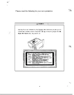
Please read the following for your own protection.

 Caution

Opening the cover indicated by the 

 label below may expose you to

harmful laser radiation which could cause damage or loss of eyesight. Do 

not

Open the Cover 

when the power is on.

iv

Содержание 2060

Страница 1: ......

Страница 2: ......

Страница 3: ...S P A 3 1 0 Service Parts Manual September 1996 Revision C 02 ...

Страница 4: ......

Страница 5: ...WARNING LABELS i ...

Страница 6: ...ousing and external covers the laser beam cannot escape from the LBP printer during any phase of user operation CDRH REGULATIONS The Center for Devices and R ological Health CDRH of the U S Food and Drug Administration implemented regulations for laser products on August 2 1976 These regulations apply to laser products manufactured from August 1 1976 Compliance is mandatory for products marketed i...

Страница 7: ...denna de1 ar oppnad och sp ren 2r urkopplad Behakta ej St en Finland Only VAROITIJS Pristo voi r jahM jos se on virheellisesti asennettu Vaihda paristo ainoastaan laitevalmistajan suosittelemaan tyyppiin H vita tiytetty paristo valmistajan ohjeiden mukaisesti 1 VARO Avattaessa ja suojalulcitus ohitettasessa olet ahtiina n ymatt lmtie lasersateilylle 4 katso sateeseen New Zealand Only Warning Immed...

Страница 8: ...wing for your own protection I A Caution 1 Opening the cover indicated by the Caution label below may expose you to harmful laser radiation which could cause damage or loss of eyesight Do not Open the Cover when the power is on iv ...

Страница 9: ...s 3 Thisprinbuisusinganinvisiblelaserbeam Topleventalaserbeamleak theprintermaLesatri runtobesurethecoversarein tion HANDLING THE P W B Observe the folIowing precautions when handling a P W B with ICs 1 During Transportation Storage i 1 During transport and storage P WB s should be kept incarductive bags or on mats and not taken out lmkss absolutely rEce ssary 2 P WBs should be stored in a place w...

Страница 10: ...Requirements A 2 B GENERAL INFORMATION 1 SPECIFICATIONS B l 2 PARTS IDENTIFICATION B 3 3 COMPONENT LAYOUT B 4 4 GEARS ROLLERS ASSIGNMENT B 5 5 ELECTRICAL CfX4POMENT LAYOUT B 6 6 CONNEcroRs LAYOUT B 7 7 SWlXElES SENSORS IDEN IlFICA N _ a B 8 8 ELECl RlCAL SERVICE PARTS ON P W BOARDS B 9 9 SYSTEM LAYOUT B 10 9 l Drive Se m B 10 9 2 ElectridSection B 11 10 SEQUENCE FLOW B 12 11 CIRCUITDIAGRAM B 13 vi...

Страница 11: ... c 9 10 2 Multiple sequence C 9 10 3 Fkdiug sequeuce c 9 104 Duplex SeqEnce c 10 10 S Power ON sequence c 10 D DISASSEMBLY CLEANING 1 MAINTENANCE INSPECTION D l l l Replacement of Parts D l 1 2 cbauiug Parts D l 1 3 Required Send Tools D l 2 DISASSDlBLY PROCE5DURE D 2 2 1 Outer cover D 2 2 2 Fusing unit D 2 2 3 Image Traasfer Unit D 6 24 High Voltage Unit D 6 2 5 Power unit D 7 2 6 Print Head Unit...

Страница 12: ...AClTON FOR DETECTED JAM OR MALILJNCI ION F 3 2 1 JAM1 F 3 2 2 JAM2 J 3 2 3 JAh43 F4 2 4 JAM4 F4 2 S Fusing unit IIlahndal ES 2 6 Laser malfuoctoo ES 2 7 Polygon Motcx malfunction s 5 2 8 Fan Motor malfunction T 5 2 9 Main Motor m on J 5 3 Ol HER DETECTED TROUBLE F 6 3 1 NoPower F 6 3 2 Skew F 6 4 IMAGE QUALlTY TROUBLE F 7 Black White lines F 7 IJtdmlltal lines P 7 LowimageDensity F 7 Fogsyb kgroun...

Страница 13: ...PRODUCT INSTALLATION 1 PREC AlJTION FOR NjlXlLATION A 1 l l Jnstallation Site A l l 2 lzLwirm td llequireme ts A l l 3 Power Requirements A l 2 INSTALLATION A l 2 1 Gmuection A l 2 2 space Requirements A 2 ...

Страница 14: ... conditi please make sme the ambii enviraunent saiis6esthefollawingn4uirements TemperahUt lOto350C Temperaturektuation rtl Cperhourculess Humidity 15to85 RH Humidity fluctuation of r2090 RH per hour or less Height o 2 5 0 0 m Atmospheric pressure 760 hPa or more I l 3 Power Requirements Do not plug the Power Cord into a power outlet via an extension cord supplying electricity to more than onelmk P...

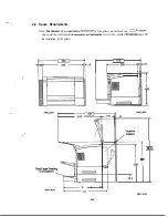
Страница 15: ...e printer are enclosed in a a TO ensure easy operation replacement of commable and main service jobs provide the fotiowing space fa the installation of the printer 15 OSS aO21 I iii t ns 175 7 0993maO24 5 2 1 0993 15 Dupiexer Kwon p 1 880 1 541 f 106 Y v Y 593 ______Ff A 2 Unit mm ...

Страница 16: ... B 4 4 GEARS ROLLERS ASSICXMENT B 5 5 ELECTRICAL COMPONENT LAYOUT B 6 6 CO ORS LAYOUT B 7 7 SWlTCBE S SENSORS IDENTIPICATION B 8 8 FXECIRIW SERVICE PARTS ON P W BOgRDS B 9 9 SYSTEM LAYOUT B 10 9 l Drive Section B 10 9 2 Ele cal section B l 1 10 SEQUENCE FLOW B 12 11 URCUlTDL4GRAM B 13 _T _I ...

Страница 17: ...e black to white ratio is 5 on multi pints ThueiStOWUnpty tif EXiiGtE3 5 ozinlc 0 04 mgh 0 02 ppm or less Dust 0 25 mghl or less LascIDiodc PolygcnlMimxscanning 64Xldpi S within5mmcdpa edge Multiprint within75mmafpaper ge SblgkpKiIlt 16saiA4C Dupkxpiint 26sec A4C shgleprint 2Osh1xtslmip A4C Duplexpint 125pagcs min A4C h fdti purposeTray 92 33Omm w x14O 483mm L A3 A4 M B4 BS Lettet Supa B size OBP ...

Страница 18: ...ter L C L lengthwise c crosswise Paper Snger system 250 sheets Ordinary Plain Paper Recycled Paper aCr90 gim2 A4 C or Letter C L lengthwise C uosswise PaF finger system 500 sheets Ordinary Plain Paper Recycled Paper 60 90 g m A3L B4L A4UC B5C A5C LetterUC 250 sheet Cat e 250 sheets maximum Paper empty 0 sheet Paper nearempty 1 50 sheets or less Paper near empty 2 250 sheets 95 6 mm sec 5V O lA 24V...

Страница 19: ...y 2 Paper Exit Tray 3 Upper Unit Lock Release Lever 4 Duplex Unit Option 5 Duplex Lower Cover 6 Interface Connector 7 33cod Cassette Unit 8 Third Cassette Unit Option 9 Imaging Cartridge 10 500 Sheet Letter Cassette Option 11 250 Shset Cassette OSS3 b024 OS93W25 B 3 ...

Страница 20: ... PE2 6 Paper Exit Roller 20 2nd Paper Near empty Sensor PNE2 7 Upper Fusing Roller 21 Paper Lifting Plate 8 Paper Exit Sensor PC3 22 3rd Cassette Unit Option 9 Lower Fusing Roller 23 2nd Cassette Unit 10 Duplex Transport Roller Option 24 ML purpose Tray 11 Duplex Paper Sensor PC4 25 Paper Take up Roll 12 Image Transfer Roller 26 Paper Empty Sensor PEl 13 Paper Take up Sensor PCl 1 Paper Near empty...

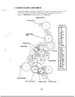
Страница 21: ...he drive to rollers aE the Duplex Unit Refer to C MECHANICAL 2 2 2nd Cassette Unit 9 2 Duplex Utit Pam Exit Roller Paper Take up Roll Trahqm Roller T ransport Gear Gear Ratios 1 20 2 77 3 75 4 39 18 5 33 6 31 22 7 38 9 6oR3 10 39 11 15 1 2 15 13 39 14 14 15 18R3 1 6 2 4 17 14 18 20 19 14 17 20 16 21 44 22 601 23 23 7Otl6 24 18 25 63 27 26 45 47 27 44 134 28 18 29 15Rl 30 44 31 25 32 31R5 B 5 ...

Страница 22: ...tor Power Fan Motor Paper Take up Solenoid 2nd Papar Take up Solenoid Registration Clutch Power Switch Interlock Switch Duplex Cover Switch 2nd Paper Size Switch PC1 PC3 PCRI PEl PNEI PE2 PNE2 H L TEI THI TSI 0963 bO51 Papar Take up Sensor Paper Exit Sensor Registration Sensor Paper Empty Sensor Paper Near empty Sensor 2nd Paper Empty Sensor 2nd Papar Near empty Sensor Heater Lamp Toner Empty Sens...

Страница 23: ...per Take up Solenoid CN8 Registration Clutch CNl E Power Switch CN3E Interlock Switch CN8A 2nd Paper Size Switch CNI OA Paper Take up Sensor CN3 Paper Exit Sensor CNl OA Registration Sensor CNGA Paper Empty Sensor CN3A Paper Near empty Sensor CN8A 2nd Paper Empty Sensor CN8A 2nd Paper Near empty Sensor CN2 YL Heater Lamp CNEA Toner Empty Sensor CN5 Therm of CIWYL Ttkmostat S _ I Duplex Unit Option...

Страница 24: ...y Sensor Detects 50 sheets ofpapesfor 2nd Cassette Unit Active 33 Detects 250 sheets of paper for 2nd Cassette Unit Active ET Detects toner empty condition Active z THl Thermistor TSl I IThermostat Function Turns powex ON and OFF Detects the paper exit ofFus Unit Active WY De da paper in Duplex Unit Active z Defects the timing of 2nd Cassette Unit Duplex Unit z I Detects paper empty condition Acti...

Страница 25: ...CE PARTS ON P W BOARDS PWB A PWB F I VRl PWB E mw y2op CN3 CNl VRlA 0 CN5 CN6 CN7 CN8 CN9 CNlO CNll r q j 7q7p1 2p1 1op1 2pll1Ip 0 I V R 3 VR5 VR6 0 2P CN2 0 r l I I 1 I CNl rl F 2 cm CN2 Fl CN5 m CN3 q RV2 C N 4 c P B 9 ...

Страница 26: ...ransport Roller Paper Take up Sensor m I I Transfer Roller I Fusing Roller Paper Exit Roller Registration Clutch a 1 1 piin Sensor Polygon Motor uw sas sgtiG iCurrent of LD 1 e Themstor I Hi khemwstat X31 1 i jt i Empty Sensor Pl2 I Switchback Motor w3 iEg sa duplex Paper Sen r VJ c4 1 T i I B 10 ...

Страница 27: ...Power line The Power source supplies DC SV and DC 24V to the main control board and AC to the Heater Lamp ThePrinterreceivesprintdataframthehostPCthroughaninterface Zhe olleradjus thesizeandpositionoftbeprint tatogenerateimage Printingoccursafter theimagedatahasbeentransmittedtothePrintHeadunitviat emain olbosrd The main control board controls the various parts of the qine Print Head unit and Dupl...

Страница 28: ... the Controller main control and d 7 engine as shown below f z cT I I Controller Interface v Command Processor I I Command Processor Host PC I I Image Processing Image Processing Image Line Memory H SYNC Line Data Main Control Standby Feeding yl Charging Exposed PM w Transfer B l 2 ...

Страница 29: ...24V S 3j 4 CN Pq w Exit s Thumistor 2nd Papu Empty sotwar 3rd Pqxr Empty s mwr i Ragiul tbn CMCh CN6A FS PM Q TEl 1 I I CN 0 7 PWB 0 dr LD Board 1 Prinl Head utdl Pdygon Motor N12A 24V kmm CNlM sv m Ram 24V tuo2 PCRl EVR iv B VR xm is HL Run CNSA NH 1 NlF CTI Uppwhoww Fusiq Fwlrr I N0l l COllt lbClbll NIE H CNPE UP I W1 i r V 8 1V IA I Hmahl Lamp PlJl PWB E h4aln Motor M l 4 I Power Svrlch PWB A i...

Страница 30: ... 3 IMAGING CARTRIDGE c 4 4 CHARGlNG c 5 5 ExEmmRE p H c 5 6 DEVELOPMENT C 6 7 TIUNSFER c 6 8 FUSING C 7 9 PAPER EXJT DUPLEX C 8 9 1 Paper Exit C 8 9 2 Duplex Option C 8 10 PRINTING SEQUENCE c 9 l0 l Starting sequence c 9 10 2 Multiple sequence C 9 10 3 millg sequence c 9 loA Duplex Print seqmce c 10 10 5 Power ON sequence C 10 ...

Страница 31: ... I PRINTING PROCESS I 9 Paper Exit Duplex I Sensor C l ...

Страница 32: ...ion ia which the amount of paper still available for use ia50sheetsor1ess 2 1 Multl purpose Tray The drive is trauami ed from the main drive motor Ml to the paper take up clutch one way clutch paper take up roll and the push down cam When the paper take up solenoid SLl is eneqixd the paper take up roll and push down cam turn one complete turn As the push down cam turns the paper lifting plate is r...

Страница 33: ... to the PC drum The paper separator fingers prevent the secmd andsubsequentsheetsdpaperfranbeingtaLenupwiththefirstane Thepapersizeswitches S4 1 2 3 and4 anthecontrolboard c tectthesizeofthepaperloadedin ay Ihecambinatiansinwhich switcbesarehrmedaoandoffarelistedbelowtorepresent k kr mpty sensor PNE2 detects a cmdition in which the amount of paper still available for use is 50 sheets cr less or 25...

Страница 34: ...RTRIDGE i The illustration below shows the c ction of the PC drum charge unit and developing tit Charse Brush Cleaning Blade Agitator Blade Pa Fuse Toner Hopper Toner Jeed Roller S eve Roller Cleaner Mirror window ...

Страница 35: ...be PC Drum by static electricity More laser exposure It applies arg directly to the PC Drum at a low voltage and tkrefore the Bmouat of ozone produced is only negligiile Charge Brush Charge bias _ Laser 5 EXPOSURE P H t Laser Diie Polygon Mirror PC Drum ...

Страница 36: ... voltage is made positive to prevent leI fram stiCkiUg to the OV alEaS LEDonPWB Gemitslightwhichisthen fl tedoffthemirroainsidethetonerhopperforuseinthe detection of a tfmer empty ccndilion Readings are taken while the Main drive motoI PWB F t Hiih Volt age Unit seal kas Ton er Feed Roller Toner Ern Se or TEl 0693 CO62 isturning leeve Roller PC Drum 7 TRANSFER PC Drum N e e d l e pole L PC Drum Tr...

Страница 37: ...edONorOFFbyasignalfromMPUou accardingtothetemperature detected by the tbermistar thereby controlling thetempenture of the upper fusing roller Whn the thermistor detects JI abnormally high temperature MKJ forces the Heater Lamp OFF PWEA in Thermistor THl Detects Analog Voltagje Thermistor Fusing Unit Temperature Control 1 During warm up The T I starts w m up to attah a temperature of approx 190 C w...

Страница 38: ...per moving past the exit sensor is fed out of the printer by the exit roller 2 When the printing cycle is completed for the front side in 24ded printing the paper is fed towards the exit by the exit roller until it moves past the exit sensor When the paper move3 past the exit sensor the switchback motor M6 is turned backward feeding the paper back to the duplex paper take up area The transport mot...

Страница 39: ...1 O 1 Starting sequecznt d hd3 Continuous 9 m I I _ Polygon Motor il 7 10000 tvl2 Take up Solenoid f SLl SU Paper Take up f Sensor PC1 1 O 2 Multiple sequence VPtint 10 3 Ending sequence vExit Sensor OFF Print ends v m sec ...

Страница 40: ...1 O 4 Duplex sequence I 10 5 Power ON sequence Trouble Check vPower ON R ist Sensor hl Pc4 Note Error check sequen C l 0 ...

Страница 41: ...Requkd Service Tools D l 2 DISASSEMBLY PROCEDURE D2 2 l Outer cover D 2 2 2 Fusiug unit I D 2 2 3 Image Transfer Unit Ix 24 High Voltage Unit D4 2 5 Power Unit D7 2 6 Print Head Unit 07 2 7 Paper Empty Sensor Assy D 8 2 8 Paper Take up Roll Assy D 8 2 9 Regismion Roller Assy D 8 2 10 Drive Unit D9 2 11 Duplex Unit D 9 ...

Страница 42: ...etection off f or 120 000 sheets of multi printing 1 2 Cleaning Parts Parts Name Cleaning Procedure Paper Take up Roll wipetheduat withasoftclothdampenedtithacahal Fusing Roller Wipethe st witha dtclothdampUXdwithaldd Image Transfer Roller Wipethesurfacewithadrypieceofsoftcloth Note Do not touch the surface of the Image Transfer Roller with the hand N l 3 Required Service Tools Tools use Driver No...

Страница 43: ...ing Unit 1 Remove the Left Cover 2 screws 2 Remove the Right Cover 3 screws 3 Remove the Upper Unit 2 screws 4 Remove the Right Front Cover 1 screw 5 Remove the Front Cover 6 screws 6 Remove the Rear Cover 2 screws 9 33 d021 1 Remove the Outer Cover Refer to section 2 l 2 Remove the Fusing Unit 4 screws 3 CoMectors 0993 d0226 Note When reassembling the Fusing Unit adjust the position of the Image ...

Страница 44: ...eater Lamp Cover turn the Cover in the clockwise direction 4 Remove the Right Heater Lamp Cover 1 screw Note When removing the Right Heater Lamp Cover turn the Cover in the counter clockwiie direction Y 6 5 HoldingtherightendoftheHeate rLamp takeout the stopper and spring 6 Pressing the Heater Lamp in the direction indicate by the arrow remove it from the heater saket D 3 ...

Страница 45: ... 1 F move the Rear Fusing Cover 2 scows 2 PushtheAodrstopperinthedirectionindiuttedby the arrow and remove the Lower Fusing Roller 1 Release the stoppers of tJle separator 2 Pulling and sliding remove the stoppers Note The two paper separator finger stoppers on the right face the opposite direction to the two on the left D 4 ...

Страница 46: ...E ring r 1 Remove the front Fusing Cover 2 screws 1 harness 2 Remove the Thermistor 1 screw 1 Remove the IYbe rmostat 2 saws 1 Remove the G ring 2 Remove the Gear Ring Bushing 3 Remove the Upper Fusing Roller as indicated by the arrow 4 Remove the Gear 1 E ring D 5 ...

Страница 47: ...ove the Outer Cover Refer to sect 2 1 2 Remove the Fusing Unit Refer to sect 2 2 3 Remove the Rear Frame 6 screws 1 connector 4 Remove the Image Transfer Unit 1 scriw Note With the Left Frame open release the Transfer Unit Pulling the Transfer Unit in the direction indicated by the arrow remove it Note Don t touch the surface of the Transfer Roller with the hand 1 Remove the Outer Cover Refer to s...

Страница 48: ...e the Outer Cover Refer to sect 2 l 2 Remove the Power Unit 6 screws 5 CoMectors 1 Remove the Outer Cover Refer to sect 2 1 2 Remove the Harness Cover 2 screws Note Pulling the harness cover to the right remove it 3 Remove the Print Head Unit 3 screws 1 connector D 7 ...

Страница 49: ...ve the Paper Take up Roll Assy 1 screw 2 9 Registration Roller Assy 0993dO822 1 RemovetbeOuterCmx efkrtosect 2 1 2 Remove the Fusing Unit Refer to sect 2 2 3 Remove the Transk Unit Refer to sect 2 3 4 Remove the High Voltage Unit Refer to sect 24 5 llemwe the Paper Empty Sensor Assy Refer to sect 2 7 6 Remove the Paper Lifting Plate 1 screws Note Move the printer Left Frame in the direction of the...

Страница 50: ...2 3 Remove the Transfer Unit R x to sect 2 3 4 Remove the High Voltage Unit Refer to sect 2 4 5 RemovethePapezE nptySensorAssy eferto sect 2 7 6 RemovetheRegistr Roll hsy Wertosect 243 7 Remove the Drive Unit 5 screws 7 cumectm 1 Loosen 2 SLxews 2 Remove the Duplex Unit Note At reinstallation position the two positioning pins coupling gear and coupling amnector correctly D 9 ...

Страница 51: ...E ADJUSTMENT 1 IMAGE REGISTRATION E 1 ...

Страница 52: ... ...

Страница 53: ...st the gap by fouo g the pr hbd 7 below 1 Paper Reading Edge t Registration position Gapd PWB A 1 Remove the Light Fret Cover efex to the Dz Disassembly Clean item 2 l 3 Another adjustment Adjust the VRlA so that the Voltage is 250V between VRlA and ground terminal E l ...

Страница 54: ...TED JAM OR MAJXUNCI ION F 3 2 1 JAM1 F 3 2 2 JAM2 F 3 2 3 JAM3 F 4 2 4 JAM4 F 4 2 5 Fusing Unit malfixuztion F 5 2 6 Laser malfunction F 5 2 7 Polygon Motor malfunction F 5 2 8 Fan Motor malfunction F 5 2 9 Main Motor maH nction F 5 3 OTHERDETECIXD TROUBLE F 6 3 1 NoPower Fd 3 2 Skew F 6 4 IMAGE QU TROUBLE F 7 BklC WWhikl iIleS F 7 Horizantal lines F 7 Low Image Density F 7 Foggy background F 7 No...

Страница 55: ...8 sec after the leading edge of the paper has nz ed the Paper Take up Sensor Xl JAW 6 ThePaper tSensor P 33 isinthedeactivatedstateapprox 2 3sec afterthe edgeofthepaper has reached the Papet Takeq Sensor Xl JAFM r 7 ThePaper tSensor isintheactivatedstateapprox 2 3sec afferthetrairingedgedthep z has moved past the Paper Take up Sensor Cl JAM3 8 ThePaperEjcitSensor PC3 isintheactivatedstatewheathePw...

Страница 56: ...Tbeprinter thattbereisapolyganmotarmalfunctiaawhenanyafthtfollowingthreeconditionsis d edected 1 Thepolygcmmdarladrsignal energizedwithin1O Osec alterthem beenenergized 2 WhenthePolyganMotcaisON thelodcsignalswitchesONthm nxnainsOFFfarmorethan1sec 3 The SOS signal is not output during printing time l 5 Fan Motor malfunction l AfusingfanmotormaIfunctianis tedwhenthevoltageusedtodetectthefusingfanmo...

Страница 57: ......

Страница 58: ...peratthe 1 Yes Istherepaperatthe YeS IDuplex Paper t l Registration sensar 0 sensor Pm 3 I I No I No I No I No No No DocsthePaper yes Exit Roller rotate L b ward No Replace the Transport N MO W I Duplex Unit Does the Switchback Motor M6 rotate YeS No Reassemble the DuplexuJlit Re ce thei Switchback No Motor M6 Jhplex Unit No F 4 ...

Страница 59: ...o l at63 Lamp Fuse F2 TherInoStat flS1 Power unit Ho Fusing unit1 m E 2 6 Laser malfunction Refer to section 2 7 Polygon Motor malfunction 2 7 Polygon Motor malfunction ReplacetheMaiIl Control Board I 2 8 Fan Motor malfunction No Replace theMain CmtilBoard EWB A t Replace the Power Fan Motor hl4 No 2 9 Main Motor malfunction ikcurely plug in No Replace the Main No ReplacetheMain umnectiCNSA c Moto...

Страница 60: ...ug in the power 3 Yes 4 power cord to the printer cord to the AC outlet 3 2 Skew Papxisfedfiomtk No Multi purpose tray Paper is fed from the2ndCassetteor I 3rd Cassette7 YaS YeS Make sure the separators are cmrectly positioned over the paper in the cassette No I 1 Wipe the Fusing Unit a replace 2 Wipe the Paper Exit Roller 3 wii theRegistr Roller I No I Replace the Duplex Unit F 6 ...

Страница 61: ......

Страница 62: ...e the High Voltage unit PWB E Replace the Imaging Cartridge Low developing bias Replace the High Voltage unit PWB E Change the Imging Cartridge Offset Image Improper transfer Clean the Transfer unit 3 the Fusing unit Improper transport WipethedustoEoftheFusingRollex F 8 ...

Страница 63: ...I micro ac3008 0993 a021 toTMa _A _ r P _I Newsprint 2 5 Rev B J 2 5 Rev B A Openwin library 3 Tue Am 16 14 02 02 1996 I NeWSprint interpreter 210 0 I Print Messages _ Page 1 of 1 Broken 6 1 e ...

Страница 64: ... 0993 PARTS MANUAL MINOLTA QMS ...

Страница 65: ...he illustration such as an electrical part or a part which varies according to market ares has two or more part numbers The second of the I WO letters represents the modification hislory of that part 4 The Area Number is listed in the Area Column for only those parts used in certain market areas This Area Number represents the area listed opposite to it in the Chart given on Page If Parts having n...

Страница 66: ... i WNo kt Z Z AREA No AREA JII f No A i i JCL4 AREA No JB h 1 No JAPAN 0 I4 We recommend that you cross out from your Parts Manuals those parts numbers which do not apply to your area 0 that no error is made when ordering parts ...

Страница 67: ...2 5 1 5 PAPER TAKE UP SECTION j j g R g5 0 7 DRIVE UNIT I gj 5 g TRANSPORT SECTION i 5 5 1 1 FUSING UNIT 2 s 13 2ND CJRD BIN UNIT T s B 1 y b 15 UNIVERSAL ASSET j E xz jJLfie y 17 CASSE TE fi y j 19 DUPLEX UNIT pJgjg ff y b 21 WIRING ACCESSORIES AND JIG 5 2 23 SCREWS AND WASHERS 2 y 7 y 5 r 25 24 NUMERICAL INDEX I 25 _ m ...

Страница 68: ...L H O U S I N G 9C 3 PARTS MANUAL ...

Страница 69: ... 1521 02 993 2017 03 993 1016 02 993 2009 01 993 1021 01 993 1004 03 993 1005 01 993 1009 01 993 1002 02 993 2304 01 993 1006 01 993 3208 01 993 3209 01 993 3210 01 993 3205 01 993 3211 01 993 3206 01 100 1212 04 993 1011 01 1993 0754 01 PART NAME SK OP C O V E R bInI HAFT rr k IOLL XCER IEAR COVER wlhJ i OUn0 P L A T E I XJ r IEINFORCE P L A T E t 131 3 iEUTRALIZING BRUSH ye I S USHING L COVER 7 ...

Страница 70: ...FRAMES 7 L J P PARTS MANUAL ...

Страница 71: ...A A 3993 2602 02 2CAA 993 2042 02 25A4 3993 204L 01 2 6 A A 993 2043 02 2 7 A A 1993 2606 01 28AA 3993 2607 01 PART NAME tfl I 8 1s t 3 I POWER CORD f 3 f POWER CORD f S 3 SOCKET Y l Jk HARNESS II X T E N S I O N S P R I N G tv J1Y J 7 y HOLDER lbz T O R S I O N S P R I N G 5 JX7 d 7 S U I T C H Eh F R A M E t2 J L L HARNESS I 7 FAN MOTOR Z KATE 9 f r SHOULOER SCREU 4 zJ L i4EESS R T FRAHE 2 7L 6 ...

Страница 72: ...1 PARTS MANUAL1 5 ...

Страница 73: ...ITCH m t b JY71 TORSION SPRING Lb Jl J57 T E N S I O N S P R I N G tvd J13 Ji7 STUD i 29160T pi 2 4 T s r u o C 7 PLATE 3 23T ON S P R I N G II JXT J 9XLE P L A T E 4 7r it _Ei NAL E NAL A TERMINAL d lflb TERMINAL ON S P R I N G 33 J Z J 7 FE p PRESSURE SPRING x x JCJP L I F T I N G P L A T E t977 r RACK GEAR j J7 7 E 1 4 T GUIDE LFT t9 Jh f E WW TOR M ms TOR G U I D E R T P J fr fARHESS 52 P U B ...

Страница 74: ...P A P E R T A K E U P SECTlONfi ff 3 II P A R T S M A N U A L 7 _ __ __ OS 8 _ _ _ _________ 1 8 4 I I I I I i ...

Страница 75: ...0993 3039 01 2SAA 0957 3015 01 2 6 A A 0993 3022 01 2 7 A A 993 3014 02 28AA 993 3013 01 2 9 A A t993 3021 02 SOAA 993 3017 02 3lAA 1993 0751 01 32AA 1993 3521 01 3 3 A A 993 0411 01 iUitlINC 9 797 T E N S I O N S P R I N G t JX7 J 7 B U S H I N G 3 7 7 7 O LE G R O L L E R i ND P L A T E 7 all 3 E fE S E T P L A T E 19IJ P R E S S U R E S P R I N G 7 5r717 J 7 S U P P O R T 9 r i kER FE B U S H I...

Страница 76: ......

Страница 77: ...515 01 1993 2519 01 1993 2508 01 1993 2506 01 1993 2503 01 t993 2510 01 t993 2511 01 t993 2514 01 t993 6205 01 1993 2512 01 993 2504 01 1993 2505 01 993 2524 01 0993 2501 13 D993 ZSlJ 01 9993 2507 01 1993 0202 01 t993 2536 01 t993 6204 01 993 6101 01 t993 0201 01 993 0151 01 1 9 9 3 2 0 2 6 0 1 1993 2035 01 1993 2040 01 3993 6825 01 1052 7257 01 CL11 SLl Ml TY 3R r 1 1 1 1 1 1 1 1 1 1 1 1 1 1 1 1 ...

Страница 78: ...T R A N S P O R T SFCTION 2 9 E PARTS MANUAL L ...

Страница 79: ......

Страница 80: ......

Страница 81: ......

Страница 82: ......

Страница 83: ......

Страница 84: ...0 a P A R T S M A N U A L ...

Страница 85: ...15 01 ClSb 3914 01 ClSb 3911 01 4156 3918 O ClSb 3912 01 156 3906 05 lSb 3922 01 lSb 7301 01 PART NAME I I 8 i COVER RT 5 a PAWL I3 GUIDE R1 fi fE MJ TOR PRESSURE SPRING J a lX 137 L I F T I N G P L A T E 277 r t G U I D E L F T t Jh f k PAUL C ER LFT t P Jb CASSETTE BODY hh7 b t l GROUND PLATE XII R 141 RACI G E A R 577 7 D E T E C T I N G P L A T E 73ClYli y LID 4 R COVER I LATIKG P L A T E SCff...

Страница 86: ... 4 ...

Страница 87: ... ...

Страница 88: ......

Страница 89: ... S P R I N G IYe JZJ jP fE COVER SURE S P R I N G 701713 J 7 EiY SHOULOER SCREW 2 COVER LDER SCREW J 3 GROUND PLATE 1ll j g EASE a SWITCH 14Yf tP c PRESSURE SPRING 7 1717 Jc 7 BRACKET b Y7f 3 T O R S I O N S P R I N G Xtr JX J P tA OR SHOU DiR SCREW p y 3 YJl 5 B E A T S I N K t3 7rl IiOTDR G oA L B WITH Y J b J 8 GROUND PLATE Xl H E A T S I N K t32Yt 3 G E R 11138T fE 22T T E N S I O N S P R I N ...

Страница 90: ...s 8 i laas5tarn 4 OZBA 9384 1310 81 UIRINC S A D D L E 6 4H 1 7 74V YE ib 02CA 9 3 8 4 1 9 0 0 6 4 W I R I N G S A D D L E 13 OH 2 7 b Yb C OZDA 9384 1900 65 i f_ ADDLE 18 0H 3 03AA 9384 2600 11 EDGE COVER 26H 1 17L hl OCAA 9 3 8 4 2 8 0 0 3 6 E D G E C O V E R 1SH 4 I Jb hll s 04BA 9384 2010 21 E D G E C O V E R 8 5H 1 I hrt ...

Страница 91: ...50 PbCt OC08 21 I B 1124 1305 1308 1312 1318 9646 0306 13 9646 0308 13 9646 0316 13 9646 0408 13 9102 9721 0200 01 910s 9721 0300 01 9107 9721 0400 01 910 1 9721 0500 01 9112 9721 0600 01 TAPPING SCREW 1 t 7 1 330s 9732 0308 13 NO 3411 343 3501 3SOC 3505 3508 3 19 3542 3704 370s 3709 9733 0310 13 9733 0408 13 9733 0330 13 973S 0306 13 9735 0308 13 9735 0310 13 9735 0608 13 9735 0312 13 9735 0320 1...

Страница 92: ......

Страница 93: ... ...

Страница 94: ......

Отзывы: