RIPTIDE TERROVA
BOW-MOUNT TROLLING MOTOR
OWNER'S MANUAL
Страница 1: ...RIPTIDE TERROVA BOW MOUNT TROLLING MOTOR OWNER S MANUAL...
Страница 2: ...y aspect of a Minn Kota trolling motor is thought out and rethought until it s good enough to bear our name Countless hours of research and testing provide you the Minn Kota advantage that can truly t...
Страница 3: ...tteries 17 Connecting the Batteries in a Series 18 MOTORWIRINGDIAGRAM 20 USING ADJUSTINGTHEMOTOR 22 Mount Features 22 Stowing and Deploying the Motor 23 Push to Test Battery Meter 24 Adjusting the Dep...
Страница 4: ...ts of battery s and or motor Always disconnect motor from battery s before cleaning or checking the propeller Avoid submerging the complete motor as water may enter the lower unit through control head...
Страница 5: ...MITEDWARRANTY Thecost of normal maintenance or replacement parts which are not in breach of the limited warranty are the responsibility of the purchaser Prior to using products the purchaser shall det...
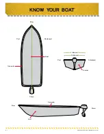
Страница 6: ...6 2016JohnsonOutdoorsMarineElectronics Inc KNOW YOUR BOAT Keel Bow Hull Bow Stern Stern Port Port Starboard Starboard Gunwale Gunwale Transom Inboard Outboard...
Страница 7: ...r from your actual motor Adjustable Depth Collar Steering Housing Lifetime WarrantyFlexible Composite Shaft CoolQuiet Power Motor Depth Collar Knob Propeller Stow Deploy Lever Fall Away Ramps BATTERY...
Страница 8: ...0 PROP WW2 3 5 8 REAMED 1 2341160 PROP WW2 4 5 W ADP RING 1 2331160 PROP WW2 4 W ADP RING 1 BB 1378131 PROP IND 2091160 WDLS WDG II 1 CC 1378160 PROP KIT 2341160 112 WW2 1 DD 1378132 PROP IND 233160 W...
Страница 9: ...ed Consider a quick release or adapter bracket with the installation of your motor 3 Phillips Screw Driver Drill 9 32 Drill Bit 7 16 Box End Wrench A second person to help with the installation TOOLS...
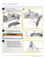
Страница 10: ...ther the Port or Starboard side of the boat based on personal preference Check placement with the motor in the stowed and deployed positions Review the mounting considerations at the beginning of the...
Страница 11: ...evel Use the Rubber Washers Item 4 provided to create a level surface if necessary i It is recommended to mark at least 4 of the 6 holes in the Base Extrusion and to have a minimum of two bolts on eac...
Страница 12: ...e Extrusion l Place a Flat Washer Item 2 and then a Nylock Nut Item 3 at the end of each screw as shown and secure Make sure all hardware is secure 7 ITEM S NEEDED 1 x 6 2 x 6 4 x 6 3 x 6 Screw Rubber...
Страница 13: ...ss of the number of cables present Use the following instructions to properly route cables Cables are shielded to minimize interference To protect this shielding the cables should not be pulled tight...
Страница 14: ...able if equipped may cause damage to the product and void your product warranty Route cables away from pinch points or other areas that may cause them to bend in sharp angles Routing the cables in any...
Страница 15: ...mp Draw Circuit Breaker Wire Extension Length 5feet 10feet 15feet 20feet 25feet 30 lb 30 50 Amp 12 VDC 10 AWG 10 AWG 8 AWG 6 AWG 4 AWG 40 lb 45 lb 42 10 AWG 8 AWG 6 AWG 4 AWG 4 AWG 50 lb 55 lb 50 60 A...
Страница 16: ...he electrical system of your trolling motor voiding your warranty Review your charger s manual carefully or consult the manufacturer prior to use to ensure your charger is compatible Minn Kota recomme...
Страница 17: ...nics The only trolling motor battery that is safe to connect to one of these systems is the Low Side Battery NOTE The internal bonding wire is equipped with a 3 amp fuse Improper connections described...
Страница 18: ...stems Three 12 volt batteries are required The batteries must be wired in series only as directed in wiring diagram to provide 36 volts 1 Make sure that the motor is switched off speed selector on 0 2...
Страница 19: ...Systems Three 12 volt batteries are required The batteries must be wired in series only as directed in wiring diagram to provide 36 volts 1 Make sure that the motor is switched off speed selector on 0...
Страница 20: ...36v 12v Battery 1 Battery 1 Battery 2 Black B Red B Red B Black B Red B Battery 1 Battery 2 Battery 3 Foot Pedal Spot Lock Sensor Speed Adjustment Sensor AutoPilot Red Spot Lock Blue Constant Green Fo...
Страница 21: ...Red B Red B Black B Red B Battery 1 Battery 2 Battery 3 Foot Pedal Spot Lock Sensor Speed Adjustment Sensor AutoPilot Red Spot Lock Blue Constant Green Foot Pedal Control Board Foot Pedal Attachment...
Страница 22: ...or is stowed Power Button The Power button is located on the Indicator Panel on the Mount The Terrova must be manually powered on and off When the Motor is powered on the Power Indicator will be illum...
Страница 23: ...it against the top of the Lift Assist Housing to secure the motor in place and prevent accidental deployment WARNING When stowing or deploying the motor keep fingers clear of all hinge and pivot point...
Страница 24: ...d on the Indicator Panel on the Mount of the motor The Battery Meter provides an accurate display of the remaining charge in the battery It is only accurate when the motor is off The meter reads as fo...
Страница 25: ...NG The Control Head will create a pinch point if the Depth Collar Knob is loosened and the Control Head slides to the top of the Depth Collar Grasp the Shaft and prevent it from sliding all the way do...
Страница 26: ...Depth Collar Depth Collar Knob Shaft Lower Unit Fall Away Ramps Lift Assist Housing CAUTION The Lower Unit should be placed on the Mount Ramps every time the motor is transported If the Lower Unit is...
Страница 27: ...e two tie wrap cables to secure the Transducer Cable to the Shaft just above the Lift Assist Collar and just below the Control Head d Run the Transducer Cable through the Coil Cord to the power supply...
Страница 28: ...the prop will not turn In audio mode 2 an audible beep is heard for each increment when changing speed Attempting to go higher than speed 10 or lower than speed 0 will result in the speed not changing...
Страница 29: ...e For instance AutoPilot can be turned on or off from the remote while speed is being adjusted on the foot pedal If the momentary button is being held down on the corded foot pedal steering adjustment...
Страница 30: ...time the receiver is powered up and there are no remotes learned All 5 Beeps Foot pedal speed control is moved after speed has been adjusted with remote All Steady Tone Heard while holding down the Le...
Страница 31: ...ver To Learn Remotes To Erase All Remotes from the Receiver a Using a small blunt object such as a pen or screwdriver press and hold the Learn Button located on the side of the receiver b The receiver...
Страница 32: ...d yourself by touching a grounded metal object in order to discharge any static electricity in your body b Remove the four screws on the bottom of the remote case c Separate the case halves to access...
Страница 33: ...eg Battery Retaining Fingers Retaining Fingers Battery Remote Case Front Remote Case Back Remote Case Front Remote Case Back f Position the back of the remote case so that the Alignment peg is towards...
Страница 34: ...you will need to hold the shaft stationary with a flat blade screwdriver pressed into the slot on the end of the shaft while you loosen the Prop Nut e Align the new Propeller with the Drive Pin f Inst...
Страница 35: ...tery to full charge prior to use Keep battery terminals clean with fine sandpaper or emery cloth flooded lead acid only The propeller is designed to provide weed free operation with very high efficien...
Страница 36: ...h the switch in the Constant Mode CON position If remote has been taken apart the keypad and top case may have been installed backwards Take remote apart See the Replacing the Battery section of this...
Страница 37: ...from the WEEE Directive requirement This symbol WEEE wheelie bin on product indicates the product must not be disposed of with other household refuse It must be disposed of and collected for recyclin...
Страница 38: ...t 15 of the FCC Rules These limits are designed to provide reasonable protection against harmful interference in a residential installation This equipment generates uses and can radiate radio frequenc...
Страница 39: ...140 A Q 2 Motor Parts Diagram 12 volt 3 625 24 volt 4 36 volt 4 5 RIPTIDE TERROVA 55 80 112LBSTHRUST 12 24 36VOLT 54 60 72 SHAFT The parts diagram and parts list provides Minn Kota WEEE compliance di...
Страница 40: ...iPLT 1 6 RT TERROVA I PILOT RECEIVER 1 N 2774068 t MOTOR KIT iPLT 3 0 RT TERROVA I PILOT LINK RECEIVER 1 BB 1378131 PROP IND 2091160 WDLS WDG II 3 625 55LB THRUST 1 CC 1378160 PROP KIT 2341160 112 WW...
Страница 41: ...HRUST 4 112LB THRUST 4 5 1 56 2262658 PIN DRIVE 1 X 3 16 S S 55LB THRUST 3 625 1 58 2151726 WASHER 5 16 STD S S 55LB THRUST 3 625 1 60 2091701 WASHER PROP LARGE 80LB THRUST 4 112LB THRUST 4 5 1 62 219...
Страница 42: ...V 4 80 WW2 80LB THRUST 4 0 1 112 2 100 245 ARMATURE ASY 4 5 LWR UNIT 112LB THRUST 4 5 1 114 140 010 BEARING BALL 55LB THRUST 3 625 80LB THRUST 4 0 1 116 140 014 BEARING BALL 6000 112LB THRUST 4 5 1 11...
Страница 43: ...0 1 184 582 016 CLIP RETAINING SONAR 112LB THRUST 4 5 1 186 973 025 SPACER BRUSHPLATE 80LB THRUST 4 0 2 188 992 010 WASHER BELLEVILLE 80LB THRUST 4 0 2 190 992 011 WASHER BELLEVILLE 112LB THRUST 4 5 2...
Страница 44: ...72 366 358 346 348 350 356 352 362 318 316 328 270 334 336 338 340 342 332 296 298 292 290 288 310 322 324 354 364 344 360 VV WW XX SS CCC TT UU 488 GGG EEE DDD 44 2016JohnsonOutdoorsMarineElectronics...
Страница 45: ...N DR HSG STAGE 4 1 286 2321730 SPACER GEAR CLUSTER 1 288 MOTOR STEERING 12V FW T2 1 MOTOR STEERING 24V FW T2 1 MOTOR STEERING 36V FW T2 2 290 2302240 PINION GEAR DR HSG STAGE 1 1 292 2322520 CASE MOTO...
Страница 46: ...5 INCNL 1 2997904 ASSEMBLY HUB SPRING 80 INCNL 1 2997905 ASM HUB SPRING 112 INCN 1 350 2322300 GUIDE DR DOG LIFT ASSIST 1 352 2328605 ENGAGEMENT DOG LIFT ASST 1 354 2322725 SPRING COMPRESSION 360 OD S...
Страница 47: ...546 482 498 538 548 520 518 516 586 520 532 550 516 518 480 508 572 600 506 502 554 566 548 616 618 620 AA ZZ AAA BBB 606 558 592 588 590 608 584 582 614 512 498 614 496 552 486 630 540 626 624 628 60...
Страница 48: ...ER RELEASE LEVER BRASS 1 510 2073408 SCREW 1 4 20 X 7 8 PPH S S 1 512 2321941 BRACKET STRAIN RELIEF SW 1 514 2321951 BRACKET SIDEPLATE SW 1 516 2323412 SCREW 8 18 X 25 PPH SS TY B 4 518 2321706 WASHER...
Страница 49: ...LEFT 1 586 2205512 DECAL SIDEPLATE SW ULTERRA T2 2 588 2326531 HOUSING CENTER RT ST 1 590 2325653 DECAL BM CN PWR STATUS SW 1 592 2074082 BATTERY METER 36V SW 1 2074081 BATTERY METER 24V SW 1 2074080...
Страница 50: ...WATER 1 628 2305403 SHRINK TUBE 500 IDX1 0 ADHSV SALTWATER 4 630 2332104 SCREW 1 4 20 X 5 8 S S 1 632 2323402 SCREW 1 4 20 X 375 T L ZP 2 This part is included in an assembly and cannot be ordered ind...
Страница 51: ...protect and extend battery life TALON SHALLOW WATER ANCHOR Talon deploys faster holds stronger and runs quieter than any other shallow water anchor Available in depths up to 12 and bold color options...