Minka Group F517L-WH Скачать руководство пользователя страница 19

9

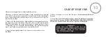
OPERATING THE REMOTE CONTROL/WALL CONTROL

Restore Power to Ceiling Fan.

A.                 Buttons: 
These buttons are used to set the fan speeds as follows;
                = Low Speed
                = Medium Speed
                = High Speed

B.      Button: 
This button turns the fan off.

C.            Button:
These buttons turn the light ON or OFF and also control 
the brightness settings of the light. The following  

instructions apply to ceiling fans that feature a DOWN 
light (     button) only or ceiling fans that feature an UP 
light (    button) and a DOWN light (    button) that are 
controlled independent of each other;
 
Press and release the button for the desired light to turn 
the light ON or OFF. Press and hold the button to set the 
desired light brightness. The light will cycle between 
bright and dim settings as long as the button is pressed. 
The light key has an automatic auto-resume feature that 
allows the light to remain at the same brightness as the 
last time it was turned off.

D. OFF-ON Slide Button (Wall Control Fans Only)
 This button turns the power Off and On to the Fan and 
Light(s).

E.          Button: (Full Function Remote Control Units Only)
This button is used to change the direction of the 
rotation of the blades; forward for warm weather or 
reverse for cool weather.

NOTE: If your Remote Control or Wall Control does not 
have a "        " button, Please look for a slide reverse 
switch on the motor housing. 

Remote Control only: Install a A23 12 volt battery (included). To prevent damage to transmitter remove the battery if not used for long periods of time.

Содержание F517L-WH

Страница 1: ...INSTRUCTION MANUAL WARRANTY CERTIFICATE U S Patent 7 008 192 CONCEPT I 52 BY...

Страница 2: ...al and or State Law including Patents Trademark and or Copyright Laws 2019 Minka Lighting Inc Manual design and all elements of manual design are protected by United States Federal and or State Law in...

Страница 3: ...Aire ceiling fan excluding wall controls and electrical components to the original purchaser or user The warranty is voided with the use of any non Minka Aire electrical devices E g wall controls or...

Страница 4: ...claim Replacement is subject to availability of the same model If the model is unavailable it will be replaced by one of equal value This is a limited warranty the original purchaser or user is respo...

Страница 5: ...ROL CARE OF YOUR FAN TROUBLESHOOTING SPECIFICATIONS 1 2 3 4 5 6 7 8 9 10 11 12 SAFETY RULES PACKAGE CONTENTS INSTALLING THE FAN HANGING THE FAN ELECTRICAL CONNECTIONS FINISHING THE INSTALLATION 1151 W...

Страница 6: ...l 5 If you are mounting the fan to a ceiling fan outlet box use a U L Listed metal octagonal outlet box marked Acceptable for Fan Support Secure the box directly to the building structure The outlet b...

Страница 7: ...SONAL INJURY DO NOT BEND THE BLADE HOLDERS WHILE INSTALLING BALANCING THE BLADES OR CLEANING THE FAN DO NOT INSERT FOREIGN OBJECTS BETWEEN ROTATING FAN BLADES TO REDUCE THE RISK OF FIRE OR ELECTRONIC...

Страница 8: ...or housing ass y 6 14W LED light kit 7 Glass Shade 8 Metal light cover for optional use 9 Standard downrod ass y 10 Receiver includes 6 wire nuts 11 Hand held remote with 2 Screws 12 Balancing kit A M...

Страница 9: ...plastic outlet box Figure 1 2 and 3 are examples of different ways to mount the outlet box Note You may need a longer downrod to maintain proper blade clearance when installing on a steep sloped ceili...

Страница 10: ...tor Assembly Fig 6 Step 3 Remove the Hanger Ball from the Downrod Assembly by loosening the Set Screw and removing the Cross Pin Fig 7 Step 4 Carefully feed fan wires up through the downrod Fig 8 Thre...

Страница 11: ...IRES Fig 7 Fig 8 Fig 6 Fig 10 REGISTRATION SLOT CROSS PIN HANGER BALL DOWNROD HITCH PIN LOCK PIN SET SCREWS SET SCREW Fig 9 DOWNROD CANOPY SET SCREWS HITCH PIN LOCK PIN COUPLING COVER OUTLET BOX HANGE...

Страница 12: ...ncy Step 1 Attach receiver to the motor housing using the double sided tape pre attached to the receiver Fig 12 Step 2 Motor to Receiver Electrical Connections Connect the WHITE wire from the fan to t...

Страница 13: ...plastic wire nuts provided Fig 13 Step 4 If your outlet box has a GROUND wire Green or Bare Copper connect this wire to the Hanger Ball and Hanger Bracket Ground wires If your outlet box does not hav...

Страница 14: ...WHITE AC IN N WHITE TO MOTOR N GROUND GREEN CONNECT TO GROUND WIRE ON HANGER BRACKE IF NO HOUSE GROUND WIRE EXISTS OUTLET BOX BLACK HOT BLACK AC IN L BLACK TO MOTOR L RECEIVER BLUE FOR LIGHT BLUE FOR...

Страница 15: ...et and place the key hole on the canopy over the screw on the hanger bracket turn canopy until it locks in place at the narrow section of the key holes Fig 14 Step 3 Align the circular hole on canopy...

Страница 16: ...to the motor by holding the blade from the tip and gently pulling it outwards The blades should be snug to the motor housing without any up down or sideways play All blade sets are grouped by weight...

Страница 17: ...Fig 16...

Страница 18: ...he LED light kit until the LED light kit locks in place at the narrow section of the key holes Secure by tightening the two screws previously loosened and the one previously removed Fig 17 4 Raise the...

Страница 19: ...n to set the desired light brightness The light will cycle between bright and dim settings as long as the button is pressed The light key has an automatic auto resume feature that allows the light to...

Страница 20: ...airflow creates a cooling effect as shown in Figure 18 This allows you to set your air conditioner on a warmer setting without affecting your comfort Cool Weather Reverse An UPWARD airflow moves warme...

Страница 21: ...acquer to minimize discoloration or tarnishing Do not use water when cleaning this could damage the motor wood blades or possibly cause an electrical shock 3 Use a lint free lightly damp cloth or dust...

Страница 22: ...f 40 feet from the transmitting unit for proper signal transmission between the transmitting unit and the fan s receiving unit SOLUTION SYMPTOM Fan Sounds Noisy Allow a 24 hour break in period Most no...

Страница 23: ...use the wood screws provided to further secure outlet box to joist Make sure hanger bracket is secure to the outlet box screws are tight If a Balancing kit is provided follow the instructions included...

Страница 24: ...s AC power ON Press the transmitter s Stop button and hold the Stop button for 10 seconds Once the receiver has detected the set frequency the down light of your fan if applicable will blink twice th...

Страница 25: ...e typical readings Your actual fan may vary They do not include amps and wattage used by the light s 52 Fan Size 120 120 Volts Speed Low High Amps 0 243 0 517 Watts 13 47 61 37 RPM 75 183 N W 11 23 kg...

Страница 26: ...nge of Similar Models 19 84 11 Estimated Yearly Energy Cost All estimates based on typical use excluding lights PERFORMANCE AND ENERGY INFORMATION Ceiling fan airflow is measured in cubic feet per min...

Отзывы: