background image


3-14 System Preparation 

3.11.3  iVocal 

Before enabling the iVocal function, ensure that the microphone device and the ultrasound system 
is properly connected through the USB extension wire.   
Tips: If the microphone is not to be used for the moment, you can put the microphone into the 
vacant probe holder temporarily. 


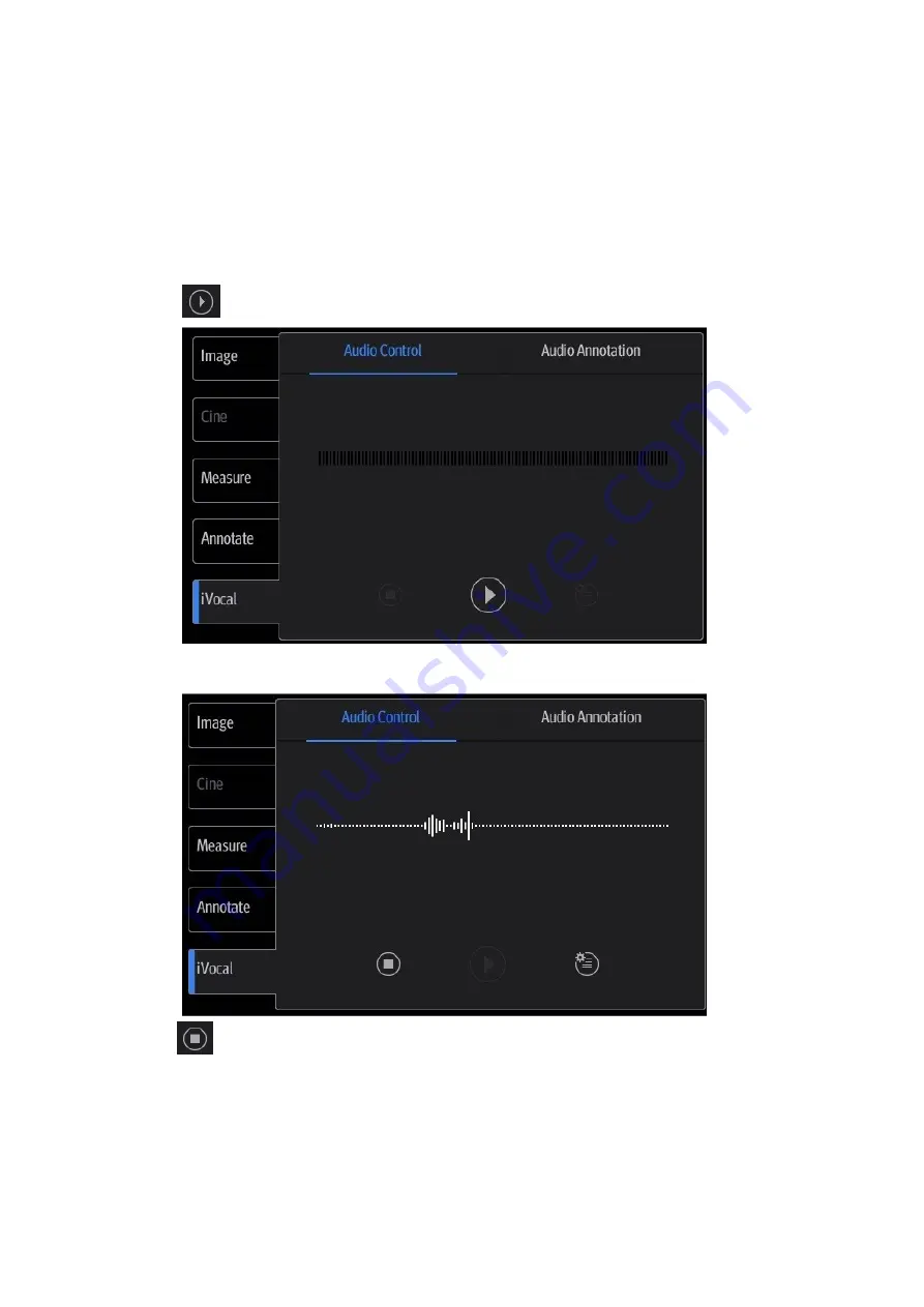
  Vocal command inputting procedures:   

1.  Tap the 

  icon in the 

Audio Control

 menu to start the vocal command recognition;   


2.  Input a vocal command using the microphone, and after the command is recognized, the 

system automatically performs the corresponding operation.   


3.  Tap the 

  icon in the 

Audio Control

 menu to pause the vocal command recognition;   

Notes:   


When the iVocal function is enabled, the system can perform 
operations both through inputting vocal commands and through 
tapping icons on the touch screen.   


The ultrasound system can automatically recognize some vocal 
commands. For details about the vocal commands, please refer to 
"17.2Appendix H List of Vocal Commands". 

Содержание TE5

Страница 1: ...TE7 TE5 Diagnostic Ultrasound System Operator s Manual Basic Volume ...

Страница 2: ......

Страница 3: ...1 2 System Overview 2 1 2 1 Intended Use 2 1 2 2 Product Specifications 2 1 2 3 System Configuration 2 2 2 4 Introduction of Each Unit 2 8 2 5 Symbols 2 10 3 System Preparation 3 1 3 1 Move Position the System 3 1 3 2 Power ON OFF 3 2 3 3 Connecting the Power Cord 3 5 3 4 Connecting a Probe 3 6 3 5 Connecting the Footswitch 3 7 3 6 Connecting USB Devices 3 7 3 7 Installing a Graph Text Printer 3 8...

Страница 4: ... Measurement 7 1 7 1 Basic Operations 7 1 7 2 General Measurements 7 2 7 3 Advanced Measurements 7 2 7 4 Measurement Accuracy 7 3 8 Physiological Signal 8 1 8 1 ECG 8 2 8 2 Parameters description 8 3 9 Annotations and Body Marks 9 1 9 1 Annotations 9 1 9 2 Voice Comments 9 4 9 3 Body Mark 9 5 9 4 Settings 9 6 10 Patient Data Management 10 1 10 1 Patient Information Management 10 1 10 2 Image File ...

Страница 5: ...Bioeffects 15 1 15 2 Prudent Use Statement 15 1 15 3 ALARA Principle As Low As Reasonably Achievable 15 1 15 4 MI TI Explanation 15 2 15 5 Acoustic Power Setting 15 3 15 6 Acoustic Power Control 15 4 15 7 Acoustic Output 15 4 15 8 Measurement Uncertainty 15 5 15 9 References for Acoustic Power and Safety 15 6 16 Guidance and Manufacturer s Declaration 16 1 17 System Maintenance 17 1 17 1 Daily Mai...

Страница 6: ......

Страница 7: ...e used only for informational or editorial purposes They are the property of their respective owners This posting serves as notice under 35 U S C 287 a for Mindray patents http www mindrayna com patents Responsibility on the Manufacturer Party Contents of this manual are subject to change without prior notice All information contained in this manual is believed to be correct Mindray shall not be l...

Страница 8: ...Malfunction or damage caused by unstable or out of range power input Malfunction or damage caused by force majeure such as fire and earthquake Malfunction or damage caused by improper operation or repair by unqualified or unauthorized service people Malfunction of the instrument or part whose serial number is not legible enough Others not caused by instrument or part itself NOTE Prescription use o...

Страница 9: ...epair performed by personnel other than those designated by Mindray 6 The purpose of this system is to provide physicians with data for clinical diagnosis The physician is responsible for the results of diagnostic procedures Mindray shall not be liable for the results of diagnostic procedures 7 Important data must be backed up on external memory media 8 Mindray shall not be liable for loss of data...

Страница 10: ...he system Hardcopy Manuals Operator s Manual Basic Volume Describes the basic functions and operations of the system safety precautions exam modes imaging modes preset maintenance and acoustic output etc Operator s Manual Advanced Volume Operator s Manual Acoustic Power Data and Surface Temperature Data Contains data tables of acoustic output for transducers Operation Note Contains a quick guide f...

Страница 11: ...menu or on the screen or buttons in dialog box square brackets indicate items in menus or on the screen or buttons in dialog boxes Tap Items or Buttons tap the corresponding item on the screen Items in menu Items in submenu select a submenu item following the path Product Differences Product model Feature TE7 TE5 Double Dist Depth Parallel line Spline length x NOTE Only TE7 is available in Canada ...

Страница 12: ......

Страница 13: ...ended by manufacturer Equipment with disinfection and sterilization method s recommended by manufacturer According to the degree of safety of application in the presence of a FLAMMABLE ANESTHETIC MIXTURE WITH AIR OR WITH OXYGEN OR NITROUS OXIDE EQUIPMENT not suitable for use in the presence of a FLAMMABLE ANESTHETIC MIXTURE WITH AIR OR WITH OXYGEN OR NITROUS OXIDE According to the mode of operatio...

Страница 14: ...Indicates a potentially hazardous situation that if not avoided may result in minor or moderate injury NOTE Indicates a potentially hazardous situation that if not avoided may result in property damage Tips Important information that helps you use the system more effectively 1 3 Meaning of Safety Symbols Symbol Description Type BF applied part The ultrasound probes connected to this system are typ...

Страница 15: ...fter turning OFF the system Otherwise electric shock may result 3 For the connection of power and grounding follow the appropriate procedures described in this operator s manual Otherwise there is risk of electric shock DO NOT connect the grounding cable to a gas pipe or water pipe otherwise improper protective grounding may result or a gas explosion may occur 4 Before cleaning the system disconne...

Страница 16: ...ns must comply with the standard IEC 60601 1 chapter 16 ME System It is the responsibility of the person who connects additional equipment to the signal input or output ports and configures a medical system to verify that the system complies with the requirements of IEC 60601 1 chapter 16 ME System If you have any questions regarding these requirements consult your sales representative 14 Prolonge...

Страница 17: ...he system with the trolley upward or downward the stairs you must separate them first and then move them individually Object placed on the display may fall and injure an individual when moving Confirm that there is no peripheral device connected to the system before moving the system Otherwise peripheral device may fall and cause injury 4 DO NOT expose the system to excessive vibration through tra...

Страница 18: ...OT connect or disconnect the system s power cord or its accessories e g a printer or a recorder without turning OFF the power first This may damage the system and its accessories or cause electric shock 12 If the system is powered off improperly during operation it may result in data damage of the system s hard disk or system failure 13 Do not use the system to examine a fetus for a long period of...

Страница 19: ...peration or accident 8 Do not apply external force to the touch screen otherwise the system may be damaged 9 If the system is used in a small room the room temperature may rise Please provide proper ventilation and free air exchange 10 To dispose of the system or any part contact Mindray Customer Service Department or sales representative Mindray is not responsible for any system content or access...

Страница 20: ...evant local regulations And manage the ultrasound gel properly to ensure that it does not become a source of infection 3 In normal diagnostic ultrasound mode there is no danger of a normal temperature burn however keeping the probe on the same region of the patient for a long time may cause such a burn 4 Do not use the carrying case for storing the probe If the carrying case is used for storage it...

Страница 21: ...turate transducers with solutions containing alcohol bleach ammonium chloride compounds acetone or formaldehyde Avoid contact with solutions or coupling gels containing mineral oil or lanolin 12 The contrast agent used must comply with the relevant local regulations NOTE 1 Read the following precautions to prevent the probe from malfunction Clean and disinfect the probe before and after each exami...

Страница 22: ...ture 0 C 35 C relative humidity 15 80 no condensation atmospheric pressure 700 hPa 1060 hPa Use the probe C4 1s under the following working conditions ambient temperature 0 C 35 C relative humidity 15 90 no condensation atmospheric pressure 700 hPa 1060 hPa 3 Repeated disinfection will eventually damage the probe please check the probe s performance periodically 1 5 Latex Alert When choosing a pro...

Страница 23: ...abels Meaning 1 CONFORMS TO AAMI Std ES 60601 1 IEC Std 60601 2 37 IEC Std 60601 2 18 CERTIFIED TO CSA Std C22 2 NO 60601 1 60601 2 37 60601 2 18 2 Read this information carefully before using the system 3 The following labels are available when the system works with the mobile trolley a Do not place the system with the mobile trolley on a sloped surface Otherwise the system may slide resulting in...

Страница 24: ......

Страница 25: ...entional superficial urology peripheral vessel adult and pediatric cardiac ophthalmic exams NOTE The functions described in the operator s manual may vary depending on the specific system purchased Only TE7 is available in Canada 2 2 Product Specifications 2 2 1 Imaging Mode B Mode B M Mode M Free Xros M C Mode Color Power DirPower D Mode PW CW Special imaging Smart 3D TDI Color M Left Ventricular...

Страница 26: ... and Weight Dimensions including probe holder 130 10 Depth x 380 10 Width x 380 5 Height mm Weight including batteries three probe socket configuration and one probe 8 2Kg 2 3 System Configuration 2 3 1 Standard Configuration Main unit select configuration between one probe socket and three probe socket Batteries built in SSD card built in System software Wireless adapter built in iScanHelper Acce...

Страница 27: ...ric Body surface V11 3Ws Convex Fetal trans rectal trans vaginal urology Transvaginal Trans rectal 7LT4s Linear Abdominal intra operative abdominal thoracic and vascular etc pediatric small organ breast thyroid testes neonatal cephalic musculo skeletal conventional superficial peripheral vessel Body surface intra operative P7 3Ts Phased Trans esoph cardiac Transesophageal L14 5sp Linear Abdominal ...

Страница 28: ...e L14 5Ws Linear Abdomen Pediatric small organ breast thyroid testes musculo skeletal conventional superficial Peripheral vessel Body surface L12 3RCs Linear Abdominal Pediatric small organ breast thyroid testes musculo skeletal conventional superficial Peripheral vessel Body surface Some of the probes have corresponding needle guided brackets for biopsy The available probes and the corresponding ...

Страница 29: ...Disposable needle guided bracket Some of the probes have corresponding disposable needle guided brackets for biopsy The available probes and the corresponding disposable needle guided brackets are listed as follows Probe model Needle guided Bracket Model L14 6Ns L12 4s CIVCO 658 001 C5 2s CIVCO 658 002 L14 5sp CIVCO 698 006 C4 1s CIVCO 698 019 V11 3Ws CIVCO 610 543 V11 3Ws CIVCO 610 1274 L14 5Ws C...

Страница 30: ...figured 8 DC IN cable ECG module should be configured 9 Travelling case After the travelling case is configured power adapter and cables must be selected 10 External DVD recorder 11 Barcode reader 12 Trolley box 13 iVocal microphone 14 CW 15 LVO 16 iNeedle 17 Abdomen General Package 18 Obstetrical Package 19 Gynecology Package 20 Cardiac Package 21 Small Parts Package 22 Urological Package 23 Vasc...

Страница 31: ...SpacialNavi 33 Contrast Imaging 34 Contrast Imaging QA 35 iWorks 36 DVR Module 37 McAfee 2 3 4 Peripherals Supported No Item Model 1 Black white video printer digital MITSUBISHI P95DW N SONY UP D898MD SONY UP X898MD 2 Black white video printer analog SONY UP X898MD 3 Digital color video Printer SONY UP D25MD 4 Barcode reader LS2208 DS4308 JADAK HS 1M JADAK HS 1R 5 Footswitch 1266262 1229155 971 SW...

Страница 32: ...th of the printers should be within 5 6 ft otherwise the lifting of the trolley will be affected if the USB cable is too short or even the ultrasound system and the printer cannot be connected or it s not easily to arrange the cable tidily if the USB cable is too long WARNING This system complies with IEC60601 1 2 2007 and its RF emissions meet the requirements of CISPR11 Class B In a domestic env...

Страница 33: ...at AC supply The indicator is off when batteries are supplied without AC supply Standby indicator Standby blinking in orange Other status light off 2 Telescoping handle Used for moving the system occasionally 3 Intra cavity probe holder Used for placing the probe 4 Probe locking switch Locks or unlocks the probe connecting with the main unit 5 Probe port Connects a probe to the main unit 6 Probe h...

Страница 34: ...ut setting resolution Setup System Peripheral Display and please make sure the scan rate of 60Hz progressive is supported by the external device otherwise malfunction may result 2 5 Symbols This system uses the symbols listed in the following table Their meanings are explained as follows Symbol Description Caution Standby Type BF applied part No user serviceable parts power adapter Battery install...

Страница 35: ...System Overview 2 11 Symbol Description Probe socket Power consumption Maximum load for printer bracket on the trolley Trolley input Trolley output Maximum load for storage bin on the trolley ...

Страница 36: ......

Страница 37: ... Switch off the power and pull out the power plug 2 Disconnect all cables from off board peripheral devices 3 Place the system in a desired location 4 Leave at least 20cm at the back and both sides of the system CAUTION Maintain a generous free air flowing space around the back and both sides of the system Not doing so may result in failure due to the increased rise in the system s operating tempe...

Страница 38: ... Conditions for details 2 There is no condensation 3 There is no distortion damage or dirt on the system and peripheral devices If any dirt is found cleaning should be performed as illustrated in section 17 System Maintenance 4 There are no loose screws on the display or the trolley 5 There is no cable damage e g power cord Maintain secure connections to the system at all times 6 The probes and pr...

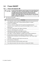
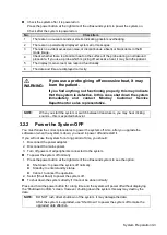
Страница 39: ...ve NOTE When you start the system or switch between transducers you may hear clicking sounds this is expected behavior 3 2 2 Power the System OFF You must follow the correct procedures to power the system off Also after you upgrade the software or when the system is down you need to power off and restart it If you will not use the system for a long period of time you should 1 Disconnect the power ...

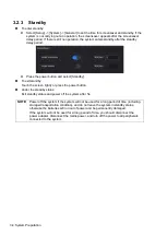
Страница 40: ...standby Touch the screen lightly or press the power button Under the standby status Exit standby status and power off the system after 5s NOTE Power off the system if the system will not be used for a long period of time including storage transportation condition and do not leave the system in standby status otherwise the batteries will run out of power and be permanently damaged If the system wil...

Страница 41: ... requirements in chapter 2 2 2 Power supply If you have any question about the power adapter please contact your sales representative NOTE You must use the specified power adapter Do not use this power adapter in conditions other than those specified 3 3 2 Powered by Batteries When connecting to the external power supply the system is powered by the external power The lithium ion batteries inside ...

Страница 42: ...G The probes cables and connectors should be in proper operating order and free from surface defects cracks and peeling Otherwise this may lead to electrical shock 1 Keep the cable end of the transducer to the right side of the system insert the connector into the system port then press in fully 2 Toggle the locking lever to the left position 3 Position the probe properly to avoid it being treaded...

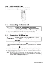
Страница 43: ... remove a USB memory device as the USB device and or the system may become damaged When connecting a USB memory device to the ultrasound system via a USB port a sound is heard if it is connected successfully and the symbol appears in the top right corner of the screen To remove the USB device tap to open the Remove USB Device screen Select the device to be removed and tap OK A sound is heard when ...

Страница 44: ...The power cord should be directly plugged into a well grounded outlet 1 Connect the data cable to the USB port on the ultrasound system 2 Power the system and the printer on 3 Put the installation optical disk of the printer driver into the external DVD R W drive 4 Install the printer driver Select Setup System Peripheral Add Printer 5 Select Add a local printer and tap Next to enter the screen us...

Страница 45: ... to this printer 4 When the connection is successful the system prompts the dialogue box tap Next according to the screen tips and then tap Finish The printer is installed successfully Tips the system has combined many types brands of printer drivers if targeted printer driver is not included in the system you may need to install the driver for the network printer Please use the optical disk or US...

Страница 46: ...r s USB port 4 Load a paper roll and turn on the system and printer 5 See section 3 7 Installing a Graph Text Printer for the driver installation procedure printer drivers listed in chapter 2 3 4 Peripherals Supported are installed already 3 9 Brightness and Contrast Adjustment 1 Tap in the top right corner of the screen to open the system tool bar 2 Drag the slider to change the brightness contra...

Страница 47: ...m Preparation 3 11 3 10 Display Position Adjustment Gently hold the bottom edge of the display when adjusting its position When positioned vertically the display can be tilted for 50 backward and 20 forward ...

Страница 48: ...1 Screen Display 1 Probe model acoustic output value and MITI index 2 Parameter area 3 iNeedle 4 iTouch 5 Frequency adjustment 6 TGC control 7 Operating panel 8 Patient Information area 9 System status icon 10 System tool bar 11 Gain control 12 Depth control ...

Страница 49: ...u downwards upwards to see parameter controls Cine review menu under frozen or cine review status Measurement menu Annotation and body mark menu 3 Exam operating area Tap each button to enter the screen Patient information Exam mode and probe switching iStation Image review Report review 4 Other buttons You can perform operations using those buttons including end exam switching modes save an image...

Страница 50: ...nu to start the vocal command recognition 2 Input a vocal command using the microphone and after the command is recognized the system automatically performs the corresponding operation 3 Tap the icon in the Audio Control menu to pause the vocal command recognition Notes When the iVocal function is enabled the system can perform operations both through inputting vocal commands and through tapping i...

Страница 51: ...n Description to select the desired function enter the user defined command in the Command text box and then select OK User defined command naming rules only Chinese characters English letters and digits are supported the English letters are case insensitive consecutive blank spaces are not supported and a maximum of 128 letters are allowed when entering the English letters Blank spaces are not su...

Страница 52: ...mand is successfully recognized by the system both the denominator and numerator of the Success Rate are added by 1 for each time if the vocal command fails to be recognized by the system the denominator of the Success Rate is added by 1 for each time through tapping the icon while the numerator remains the same For example 2 3 represents 2 times of success and 1 time of failure Clear Tap Clear to...

Страница 53: ...stem Preparation 3 17 Icon Function Audition the vocal command Delete the vocal command Rename the vocal command Add the failure time by 1 Clear the Success Rate test record of the selected vocal command ...

Страница 54: ......

Страница 55: ... exam Tips The system supports image scanning and measurement without patient information 4 1 Patient Information To start a new patient exam it is best to enter detailed patient information The system will set up a unique information database for each patient based on the patient information entered so that the information of one patient will not be confused with that of another patient CAUTION B...

Страница 56: ...4 2 Exam Preparation 4 1 1 New Patient Information The Patient Info screen is shown as follows 2 1 3 ...

Страница 57: ...s less than one year the system will automatically calculate the age in months or days You can also enter the age manually 2 Exam information Exam application type You can select from ABD Abdomen OB Obstetrics GYN Gynecology CARD Cardiac VAS Vascular URO Urology SMP Small Part and BREAST Breast Select the exam type drop down list to enter exam specific information General information Primary indic...

Страница 58: ...ill calculate the GA and EDD IVF after you enter IVF the system will calculate the GA and EDD PRV enter the date and GA of the last exam the system will calculate a new GA and EDD BBT enter the BBT the system will calculate the GA and EDD EDD after you enter the EDD the system will calculate and display the GA and LMP Gravida Times of pregnancy Ectopic Times of abnormal pregnancy e g extrauterine ...

Страница 59: ...etrieve Patient Information You can import patient information from iStation or DICOM Worklist for anonymous patients 4 1 2 1 Retrieve from iStation Using iStation the patient data can be obtained in iStation from the system hardware or USB memory device You can enter search conditions for the patient 1 In Patient screen select iStation in the bottom left corner to enter the screen 2 Select an exa...

Страница 60: ...o screen to query or import the patient data For details about the Worklist server setting see chapter 11 1 3 3 DICOM Worklist Preset chapter Worklist can retrieve patient data of two kinds of protocols DICOM and HL7 1 In Patient screen select Worklist in the bottom left corner to enter the import screen 2 Select the data source select the server type DICOM or HL7 choose a Worklist server in the W...

Страница 61: ...tap Done The patient information is imported into the system and then an exam is started 4 2 Select Exam Mode and Probe CAUTION If the exam mode is changed during a measurement all measurement calipers on the image will be cleared The general measurement data will be lost but application measurement data will be stored in the reports Selecting exam mode 1 Tap Probe on the left side of the operatin...

Страница 62: ...ons in each imaging mode see chapter 5 Image Optimization 4 4 End an Exam Be sure to avoid mixing data between patients Before examining a new patient tap End in the bottom left corner of the operating panel to end the exam of the previous patient 4 5 Activate an Exam On the iStation screen select an exam record which was completed within 24 hours and select Options Activate Exam Tips The system c...

Страница 63: ...tween Imaging Modes On the operating panel tap imaging mode buttons on the right to switch the mode Current imaging mode is indicated by highlighting the button in blue For instance the above status shows that the system is under B Color PW mode triplex is turned on 5 1 2 Image Adjustment 1 Tap Image on the operating panel to open the image parameter control menu under different imaging modes 2 Sw...

Страница 64: ...nt image settings user defined exam mode 1 Tap Quick Save in the image menu to bring out the Quick Save dialogue box 2 Enter the name in the box after To to assign a name for a user defined exam mode 3 Tap Save to save the current image parameters for the user defined exam mode Tip the Quick Save control is available under all imaging modes ...

Страница 65: ...il it floats then you can Drag upwards downwards to change its position on the image menu Drag leftwards rightwards to change its display on the image menu drag it to the left Options list to delete its display or drag it to the right Selected list to display the parameter 3 Tap Save to save the settings or tap Cancel to cancel changes you made Tip the Quick Save and Edit controls are available un...

Страница 66: ...ncy type The real time frequency value is displayed in the image parameter area in the top left corner of the screen and if harmonic frequency is used F H is displayed as the harmonic frequency value Select the different frequency values through at the left part of the image area The adjusting range of the harmonic frequency values can be divided into 4 levels penetration preferred HPen general mo...

Страница 67: ... Tap in the bottom left corner of the image area to open the TGC adjusting dialogue box There are 6 segment TGC sliders corresponding to the areas of the image Operations To increase the gain compensation in an area of interest drag the TGC control to the right To decrease the gain compensation in the corresponding area of interest drag the control to the left Double click any area on the dialogue...

Страница 68: ...ing a larger FOV B Steer Steer the probe by tapping buttons on the bottom of the image area ExFOV Extended FOV Adjust through ExFOV on the menu Off represents no ExFOV effect For linear probes the ExFOV function displays as trapezoid imaging For convex probes the ExFOV function displays as extending the scanning angle Impacts The FOV range is available only for convex and phased probes The ExFOV f...

Страница 69: ... control The system provides 8 different gray effect maps Tint Map Description This function provides an imaging process based on color difference rather than gray distinction Operations Select maps or turn on off the function by using Tint Map control The system provides 8 different color effect maps iTouch Auto Image Optimization Description To optimize image parameters as per the current tissue...

Страница 70: ...to distinguish the image boundary for optimization Operations Adjust through iClear on the menu Tap or to change the level slightly or drag the control directly The system provides 7 levels of iClear adjustment off represents no iClear effect and the bigger the value the stronger the effect Impacts It may cause increased noise Persistence Description This function is used to superimpose and averag...

Страница 71: ...erature setting is above the actual reading the system could underestimate the temperature of the TEE transducer s distal tip The patient is exposed to excessive temperatures Middle Line Description Middle Line helps to locate the focus point of shock wave during the treatment By watching the treatment procedure in real time and adjusting the intension and frequency of the shock wave the harm to t...

Страница 72: ...n M Speed M Dynamic Range During M mode imaging menus for B mode and M mode are displayed on the operating panel at the same time You can switch between the 2 modes by tapping the mode tab During M mode scanning depth focus position frequency and acoustic power of the probe are synchronous with that of B mode Adjustment of the TGC to the B mode image will lead to synchronous changes in the M mode ...

Страница 73: ...ifferent gray effect maps Edge Enhance Description This function is used to enhance the image profile so as to distinguish the image boundary for optimization Operations Adjust through Edge Enhance on the menu There are 3 levels of edge enhance adjustment available the bigger the value the stronger the effect 0 represents no edge enhance effect Impacts Larger edge enhance may lead to increased noi...

Страница 74: ...canning and adjust to position the area of interest in the center of the B mode image 2 Tap Color on the right side of the operating panel to enter Color mode 3 Change the position and size of the Region of Interest ROI 4 Adjust the image parameters during scanning to obtain optimized images Tap Image to open the image menu Adjust the parameters to optimize the image 5 Perform other operations e g...

Страница 75: ...uency Image Quality Description Refers to the operating frequency of the probe in Color mode the real time value of which is displayed in the image parameter area in the top left corner of the screen Operations Select the different frequency values through at the left part of the image area The adjusting range of frequency values can be divided into 3 levels penetration preferred Pen general mode ...

Страница 76: ...levels of packet size available 0 represents no packet size control and the bigger the value the higher the sensitivity Effects The higher the packet size the more sensitive the indication for low velocity flow Impacts Adjusting the packet size may lead to the frame rate changing Flow State Description This function is used for fast image optimization Operations Select different effects through Fl...

Страница 77: ... flow display Operations Adjust through Baseline on the menu A positive value means increase the signals above the baseline and a negative value means increase the signals below the baseline Invert Description To set the display mode of the color flow The color scale will be inverted when the function is turned on Operations Turn the function on or off using the Invert control Select Auto Invert i...

Страница 78: ...For probes L12 4s L9 3s L11 3VNs and L12 3RCs under EM Vas Vascular or Carotid exam mode using iTouch can also achieve ROI optimization and auto tracking Smart tracking ROI auto position steer in Color PW mode Description To optimize image parameters as per the current tissue characteristics for a better image effect When Smart Tracking is turned on the system optimizes ROI angle and position auto...

Страница 79: ...ers during B Power mode scanning to obtain optimized images Tap Image to open the image menu Adjust the parameters to optimize the image 5 Perform other operations e g measurement and calculation if necessary 5 5 2 Power Mode Image Parameters In Power mode scanning the image parameter area in the top left corner of the screen displays the real time parameter values as follows Parameter F G PRF WF ...

Страница 80: ...er mode image are grouped into two categories Power maps and Directional Power maps Operations Select maps by using Color Map control There are 8 kinds of maps provided P0 3 belong to Power mode maps while Dp0 3 belong to Directional Power mode maps The Power maps provide information about blood flow which are highly sensitive to the low velocity flows The Directional Power maps provide informatio...

Страница 81: ...ollows PW Sampling Line Adjustment SV Angle SVD CW Sampling Line Adjustment Angle CW Focus Depth 3 Set the position of the sample line by dragging the sampling line drag the SV gate to place the SV on the target 4 Adjust the angle and SV size according to the actual situation drag the PW angle line to change the angle pinch on the image area to adjust SV size 5 Tap PW CW Update or double click the...

Страница 82: ...he top left corner of the screen SV size Adjust SV size by finger gesture Use two fingers to adjust the SV size by pinching movement on the image area The adjusting range is 0 5 20 mm SVD Tap and drag the SV gate to change depth Effects The smaller the SV size the more accurate the result More details are obtained when selecting a large SV size CW Focus Position Description To adjust the CW mode S...

Страница 83: ...Image Optimization 5 21 Effects The higher the frequency the better the resolution and sensitivity and the worse the force of penetration ...

Страница 84: ...the left part of the image area to get iTouch optimization For L12 4s L9 3s L11 3VNs and L12 3RCs probes under EM Vas VAS and carotid exam modes you can use iTouch to optimize PW sampling line automatically Auto Calculation Description This function is used to trace the spectrum and calculate the PW CW mode image parameters The results are displayed in the results window Tap Auto Calc to turn the ...

Страница 85: ...rum can automatically invert when the color flow is steered to a certain angle to accommodate the operator s desire to distinguish the flow direction Speed Description This function is used to set the scanning speed of PW mode imaging Operations Adjust through Speed mm s on the menu There are 6 levels of scan speed available Effects Changing the speed makes it easier to identify the cardiac cycles...

Страница 86: ...playing the images V2 3 V3 2 V3 1 Full Duplex Triplex Description This function is used to set whether a B image B Color image and PW image are displayed synchronously Operations Select Duplex Triplex to turn the synchronization on or off HPRF Description HPRF mode is used when detected velocities exceed the processing capabilities of the currently selected PW Doppler scale or when the selected an...

Страница 87: ...ty to grayscale Operations Adjust dynamic range through Dyn Ra Tap or to change the value slightly or drag the control directly The adjusting range is 24 72 Effects The more the dynamic range the more specific the information and the lower the contrast with more noise PW Volume Description This function is used to adjust the output audio in the spectrum map Operations Adjust through Volume on the ...

Страница 88: ...ith an optimized B image and have the target region in mind To perform contrast imaging 1 Select the probe and the exam mode tap Image to open the image menu 2 Fix the probe 3 Tap Contrast on the right side of the operating panel to enter the contrast imaging mode 4 Adjust the acoustic power experientially to obtain a good image Tap Dual Live to activate the dual live function Observe the tissue i...

Страница 89: ...an be seen Timer 2 stops timing when an exam is frozen and after unfreezing Timer 2 is off NOTE The starting time displayed may be inconsistent with the actual one due to system error or some other human error Check the agent injecting time Activate Timer 1 2 to start timing from the moment you inject the contrast agent The screen displays the times in the bottom right corner The time begins at 0 ...

Страница 90: ...image area on the screen Mix Map This function combines the contrast image with the tissue image so that the contrast regions of interest can be located Select options besides Mix to select different mixing modes Contrast and C T When the dual live function is on you can see the mixed effect on the contrast image When the dual live function is off you can see the mixed effect on the full screen im...

Страница 91: ...gnosis Contrast Imaging QA adopts time intensity analysis to obtain perfusion quantification information of velocity flow This is usually performed on both suspected tissue and normal tissue to get specific information of the suspected tissue 1 Perform image scanning freeze the image and select a range of images for analysis or select a desired cine loop from the stored images NOTE in case of inac...

Страница 92: ...o hide or to display the QA curve To get the current X Y axis value tap Show Curve Value to activate the function and a green line is displayed Move the green line and the corresponding X Y axis value is displayed 5 7 5 2 Basic Operations of Contrast QA QA Analysis Image Range The system set the starting time and ending time of the cine to be first frame and last frame of QA analysis range Setting...

Страница 93: ...ROIs are erased from the plot Copy ROI Tap Copy ROI to create a new ROI similar to the current or latest added ROI Motion Tracking Tap Motion Tracking to enable the function This function provides a motion compensated ROI as precise time intensity information can be acquired using active tracking It can enhance the calculation accuracy as reducing the impact of probe or patient respiratory movemen...

Страница 94: ...perfectly BI Base Intensity basic intensity of no contrast agent perfusion status AT Arrival Time time point where contrast intensity appears generally the actual time value is 110 higher than the base intensity TTP Time To Peak time when the contrast intensity reaches peak value PI Peak Intensity contrast peak intensity AS Ascending Slope ascending slope of contrast the slope between the start po...

Страница 95: ...memory tap Free Xros M 2 Adjust the M mark line and image parameters to obtain optimized images and necessary information 5 8 1 2 Free Xros M Image Parameters In Free Xros M mode imaging the image parameter area in the upper left corner of the screen displays the real time parameter values as follows Display V Parameter Free Xros M Speed During Free Xros M mode imaging menus for B mode Free Xros M...

Страница 96: ...ng TVD This imaging mode provides direction and speed information of the tissue quantificationally with doppler spectrum Tissue Velocity M Imaging TVM This function assists to observe the cardiac motion through a direct angle TVM mode is also called Color Tissue M mode refer to 5 10 Color M Mode for details Only phased probe is valid for TDI function 5 9 1 TDI Exam Protocol In real time mode tap T...

Страница 97: ... 9 3 TDI Image Optimization In TVM mode adjustable parameters are the same as those in B M and TVI modes please refer to the relevant contents for details In each TDI mode parameters that can be adjusted are similar to those in the color flow modes Color PW and Power please refer to relevant chapters for details The following is to introduce the specific items in TDI mode Tissue State Description ...

Страница 98: ...M mode parameters that can be adjusted are in accordance with those in B M and Color modes please refer to relevant sections of B Color and M mode for details In Color Tissue M mode parameters that can be adjusted are in accordance with those in B M and TVI modes please refer to relevant sections of B Color and TVI modes for details In Color M mode scanning the image parameter area in the top left...

Страница 99: ...lume data 3D image MultiPlaner Rendering MPR the three sectional planes of the volume acquisition As shown in the figure below the XY paralleled plane is the C section the XZ paralleled plane is the B section and the YZ paralleled plane is the A section The probe is moved along the X axis ROI Region of Interest a volume box used to determine the height and width of scanning volume VOI Volume of In...

Страница 100: ...ne or dot of curved VOI vary depending on the view direction View Curved VOI U D At the upper part of curved VOI D U At the lower part of curved VOI L R At the left part of curved VOI R L At the right part of curved VOI F B Displays as a dot B F Displays as a dot MPR The principle of 3D imaging is to render a 3D image from multiple 2D image information The following describes the spatial relations...

Страница 101: ...e to change its position angle when performing the scan After scanning the system carries out image rendering automatically then displays a frame of the 3D image Smart 3D is an option Only probe L12 4s and L14 6Ns support Smart 3D imaging NOTE In Smart 3D image scanning if the probe orientation mark is oriented to the operator s finger perform the scan from right to left in linear scan or rotate t...

Страница 102: ... image storing processing and rendering 4 Select a render mode through the image menu Rocked mode set Angle parameter Linear mode set Distance parameter 5 Tap Update at the bottom left part of the operating panel to start the 3D image acquisition The system enters 3D image viewing status when the acquisition is completed Or end the acquisition by tapping Freeze or Update In image viewing status yo...

Страница 103: ...Capture images using Linear scan or Rocked scan Linear scanning Move the probe across the surface See the following figure Rocked scanning Rotate the probe once from the left to the right side or from the right to the left to include the entire desired region See the figure ...

Страница 104: ...vered during a fan sweep Range 10 80 in increments of 2 Render Mode Surface Function set Surface as the 3D image rendering mode This is useful for surface imaging such as fetus face hand or foot Tip you may have to adjust the threshold to obtain a clear body boundary Max Function set Max as the 3D image rendering mode Displays the maximum echo intensity in the observation direction This is useful ...

Страница 105: ... two windows are also yellow Window C is orange and the lines representing MPR C displayed in the other two windows are also orange The positions of the other two MPRs are indicated in the selected plane by color described above Display Format Tap to select the display format of VR and MPR images Single Quad and A4 1 MPR Only Tap MPR Only to display MPR only The adjustable image parameters are cha...

Страница 106: ...s and are cut out this is important in surface mode to allow a free line of sight This may or may not be the entire VOI You can adjust the view direction of the ROI a b c d e f View Direction a Up Down b Down Up c Left Right d Right Left e Front Back f Back Front Tap Up Down Left Right or Front Back to select the direction of the above Figure a c and e Tap Flip to view in the opposite direction to...

Страница 107: ...t parameters Render setting parameters description Tap to select VR or MPR parameter adjustments When VR is highlighted parameter adjustment is performed on the VR image When MPR is highlighted parameter adjustment is performed on the MPR Adjustable parameters are as follows Parameter Description Threshold Function to set the threshold for VR rendering The VR is rendered using the signal between t...

Страница 108: ...ginal parameters Render Mode Parameter Description Gray Inversion Surface Function set Surface as the VR rendering mode This is useful for surface imaging such as fetus face hand or foot Tip you may have to adjust the threshold to obtain a clear body boundary Max Function set Max as the VR rendering mode Displays the maximum echo intensity in the observation direction This is useful for viewing bo...

Страница 109: ... Zooming Zoom in out MPR and VR images by pinching the two fingers on the image Sync This function switches the view direction perpendicular to the current active plane so as to get a better view of VR Comments and Body Marks Function Add comments and body marks to the MPR and VR Operation The operation is the same as adding comments and body marks in B image mode Section image MPR measurement 2D ...

Страница 110: ......

Страница 111: ...ds to change the thermal indices The position of the focal zones may also change which may cause the peak intensity to occur at a different location in the acoustic field As a result the MI may change Use two fingers to pinch on the image area to zoom in out the image Tips for the following mode you need to tap Image B to highlight B menu first B Color B M B PW CW B Color PW CW B Power PW CW 6 3 i...

Страница 112: ... allows you to review and edit the images prior to the image being frozen This function is called cine review You can perform zoom measurements add comments and body marks on the images being reviewed The system supports manual review as well as automatic review In addition the system supports the images reviewed along with physiological waveforms if the detection of physiological waveforms is per...

Страница 113: ...view After entering cine review in 2D mode drag playback mark to review the cine images on the screen one by one Drag the playback mark to the left to display the earlier stored images drag the playback mark to the right to display the recently stored images Or swipe the image area to the right to display the earlier stored images swipe the image area to the left to display the recently stored ima...

Страница 114: ...region are saved 6 5 3 Linked Cine Review Linked cine review reviews images captured at the same moment B M Duplex mode B PW CW Triplex mode The frame mark on the time mark of the M PW CW image indicates the corresponding 2D image 6 6 Image Compare Perform the following steps to perform image compare 1 Tap iStation to enter the iStation screen and select the exam to be compared 2 Tap Compare to en...

Страница 115: ...Display Cine Review 6 5 6 Tap Return on the screen or tap Freeze to exit image compare ...

Страница 116: ...oment Images are saved to both the cine memory and the system s hard drive The live capture time can be set To perform live capture Tap Pro Capture or Retro Capture in LVO real time mode Tap Save Clip to pro retro capture the images setting path Setup System General Live Capture Save Clip Frozen image storage In frozen mode tap Save Cine 6 8 Preset 6 8 1 Setting Cine Length Select Setup System Gen...

Страница 117: ...the mode is changed during a measurement the calipers and measurement data will be cleared from the screen Measurement data will be stored in the report If the system is turned off or End is tapped during a measurement unsaved data will be lost In dual B imaging mode the measurement results of the merged image can be inaccurate Therefore the results are provided for reference only not for confirmi...

Страница 118: ...points and calculates the slope HR Measures the time of n n 8 cardiac cycles and calculates the heart rate in M mode images Velocity Calculates the average velocity by measuring the distance and time between two points D Trace On PW mode images one or several Doppler waveforms are traced to obtain the speed and PG etc D Trace Car On PW mode images in cardiology one or several Doppler waveforms are...

Страница 119: ...in 7 Circ Full Screen Within 10 Angle Full Screen Within 3 Volume Full Screen Within 12 Table 2 Basic Time Motion Measurements Parameter Range Error Distance Full Screen Within 4 Time Timeline Display Within 2 Heart Rate Timeline Display Within 5 Velocity PW mode 10 200cm s for C5 2s C11 3s L12 4s L7 3s L14 6s L14 6Ns V11 3Ws 7LT4s P7 3Ts L14 5sp L20 5s 7L4s SC6 1s 6CV1s L9 3s C5 1s C4 1s L11 3VNs...

Страница 120: ......

Страница 121: ...k 3 The ECG electrode cable must be connected to the system first Only after the cable is connected to the system can the patient be connected to the ECG electrodes Otherwise it may cause electric shock to the patient 4 Do not place the ECG electrodes directly in contact the patient s heart otherwise it may lead to stop of the patient s heartbeat 5 Do not apply the ECG electrodes if the voltage ex...

Страница 122: ...electrodes from the patient 8 Tap Physio to exit the ECG mode 8 1 2 ECG Triggering 8 1 2 1 Overview ECG triggering means that image scanning is activated at some time points of ECG signals thus obtaining B images at these time points In most cases the triggered image are 2D mode image When ECG triggering occurs a mark appears on the ECG waveform indicating the time points when the B images are cap...

Страница 123: ...he ECG electrodes connected the ECG trace is the reference for time After the images are frozen all real time images are in the status of linked review 8 1 3 2 Linked Review of ECG Signal M D Images and 2D Images If the real triggered physio signal M D images and 2D image are frozen at the same time then they will be reviewed synchronously in the linked status 8 2 Parameters description The physio...

Страница 124: ......

Страница 125: ...nu 2 Tap to put the cursor over the desired location on the image area for the annotation 3 Add a new annotation to the image in accordance with the actual situation You can modify move or delete a completed annotation Arrow tap Arrow to put an arrow on the image Type annotation tap Keyboard to enter the text typing status Select an annotation text directly from the menu 4 Tap Annotate again to ex...

Страница 126: ...otation Add change position indication select RT LT XS Sag Mid Dist Pro to indicate anatomical location 3 Tap regions other than the typed in annotation on the image area to confirm the added character The annotation changes to yellow Adding an arrow You can add an arrow to a location you want to highlight 1 Tap and an arrow will appear in the cursor position 2 Adjust the shape and position of the...

Страница 127: ...ted comment on the image area to confirm the modification and exit the edit status The annotation turns to yellow Modifying Editing Arrows 1 Tap to select the arrow that needs to be modified the arrow then turns green Change the arrow s position or change the orientation as described in Adding an Arrow in 9 1 3 Adding Annotations chapter 2 Tap regions other than the modified arrow on the image are...

Страница 128: ... exit 2 Connect the microphone to the mic port of the physic unit panel 3 Acquire the necessary images and tap Freeze to freeze the image 4 Tap iVocal Audio Annotation to enter the voice comment panel 5 Tap to start recording 6 After the voice recording ends tap the icon to end recording Tap Save Clip to save the cine NOTE in voice comment recording status you can perform measurements comments add...

Страница 129: ...he body marker menu 2 Tap to select the desired body mark to bring out the Position Probe Marker dialogue box 3 To adjust the probe position and orientation marker Tap and rotate the bold solid green line to position the probe marker Tap and rotate the dotted line to adjust the probe marker orientation 4 Tap Set to confirm the position and orientation of the probe marker and add the mark 9 3 2 Mov...

Страница 130: ...eral Setting Enter the Setup System General screen to perform the following setting You can preset whether to clear the annotations when unfreezing the image or changing the probe exam Set whether body marks are erased when the image is unfrozen Exit Setup page or changing the exam patient mode probe will clear the body marks ...

Страница 131: ... files either in the patient database in the system or to external memory devices For a saved image you can perform operations such as reviewing analyzing and demonstrating images iVision 10 2 1 Memory Media The system supports memory media including System hard disk USB memory devices USB flash drive removable USB hard disk DVD R DVD RW DVD R DVD RW CD RW CD R 10 2 2 Image File Formats The system...

Страница 132: ...M files to view rather than to edit 10 2 3 Image Storage Preset Set image size You can set the image storage size via Setup System General Set cine saving length clip length For details see 6 8 Preset Set send print image after ending the exam Select Setup System General check Sending printing after Ending Exam in the Patient Management area Then every time you tap End the system will send images ...

Страница 133: ... 1 Review an Image You can review all images stored in an exam and send delete or analyze the stored images Tap Review on the left side of the operating panel to enter Review screen or double click the exam in iStation screen Images of the current exam and the current patient are displayed The Review screen is shown as follows Controls on the Review screen Report ...

Страница 134: ...frame review for a stored image The operation steps are the same as those for real time scanning See the relevant sections for details To enter image analysis In image review status double click the selected thumbnail to open the image Tap Return to exit image analysis Other operations You can perform cine review operations in image analysis status For details see 6 Display Cine Review 10 2 6 iVis...

Страница 135: ... automatically skip files that cannot be opened Add File to add files to the file list Delete to delete selected files or catalogs from the file list Export to export selected directories files to external storage devices Interval The system automatically plays all the image files in the list one by one The time interval between images played is the same and can be changed Repetition You can choos...

Страница 136: ... devices e g USB memory devices or iStorage PC format transfer JPG AVI BMP AVI TIFF AVI Where a single frame image is exported as JPG TIFF or BMP and the cine file is exported as AVI DCM format transfer DCM including single frame DCM and multi frame DCM You can also select whether to export reports and select the report type You can select if to hide patient information For DICOM servers select th...

Страница 137: ...f Remove from local HD after backup is selected the exam are removed 3 Select whether to encrypt backup exams for USB only input the password and confirm password in the field box and then tap Backup A Patient 7z compressed package is backed up to the USB device and you need to input the password to open the package Notes 1 If the password is forgotten you cannot open the backup package 2 The pass...

Страница 138: ...t side of the operating panel b Select Preview to enter report preview screen c Tap Export to open the exporting dialogue box and select the path to export Report printing Use a connected graph text printer to print a report For details on report related operations see Advanced Volume ...

Страница 139: ...ient data includes basic patient information exam information image files and reports You can search view backup send restore or delete patient data in iStation Tap iStation on the left side of the operating panel to Enter iStation The iStation screen is shown as follows ...

Страница 140: ...nt Double click the patient exam to enter review screen you can check patient information data report and images then Tap to select the desired patient exam in the list you can Backup Restore You can back up the selected patient data to the system supported media in order to view it on the ultrasound system or restore patient data to the system from an external media For exams ended paused within ...

Страница 141: ...d images to DICOM printer DICOMDIR back up data in DICOMDIR format change the cine Compression mode and JPEG Compression mode USB storage device send exam to USB storage device Report format can be selected Format transfer is available when sending images to USB device See 10 2 7 Sending Image Files for details Print send image to the connected printer to print MedTouch send the exam to MedTouch d...

Страница 142: ...server on the right 4 Select PC transfer format to send the report 5 Tap Send to start sending 10 7Print 10 7 1 Print Setting For printer connection and driver installation please refer to 3 7 Installing a Graph Text Printer chapter Print Service Setting 1 Select Setup System Peripheral and select an existing printer service from the list on the upper part of the screen 2 Select the printer type i...

Страница 143: ...3 Select Print to print the report See the accompanying printer manuals for more details 10 8Back Up Files using the DVD Drive The system supports writing data to CD DVD using the external DVD RW DVD RW drive The system supports the following media DVD RW DVD R CD RW CD R DVD R and DVD RW To write data to a CD DVD 1 Put a CD DVD in the external DVD R W drive 2 Select the data to be backed up and t...

Страница 144: ...isplays the DICOM storage task DICOM media storage task USB devices in iStation screen select the target exam and tap Send To then select DICOMDIR in the menu which appears Back up task system relevant format select the exam to be backed up in iStation and tap Options Back Up Send to external devices USB devices select exam data or images in the iStation or Review screen Tap Send To for the image ...

Страница 145: ...ent The operator can only view exam information saved in the system and operated by him or herself such as patient information images and reports etc The operator cannot view exam data operated by others 10 10 2 Enabling Access Control The system administrator can preset the access controls that is whether an operator has the right to access data in the system Access control only can be set by the...

Страница 146: ...e using the system 10 10 4 Local Privilege Management The system administrator can add and delete users and assign privileges while the operator cannot The privileges can be assigned through the local system or LDAP server Adding a User Assigning Privilege Turn on the access control function and log in to the system as Administrator before you add the user 1 Open the Access Control page using the ...

Страница 147: ...dify all user passwords The administrator password is empty by factory default You can set this password An operator can only modify his her own password There are two ways to modify passwords on the Access Control page or in the Session Manage dialog box Access Control page administrators can modify the password 1 Open the Access Control page using the path Setup System Access Control 2 Select th...

Страница 148: ... is set to 60 and the Lockout Duration is set to 60 That is a user inputs the wrong password for 5 times within 60 minutes the account is locked and the user can log in to the system only after 60 minutes Other users with unlocked accounts can still log in to the system normally Reset Account Lockout Threshold after Set the duration allowed for a user to continuously input the wrong password Locko...

Страница 149: ...d policy The administrator can change password for administrator or operator via Setup System Access Control If the strong password is enabled and you add a new user account the system prompt an error message to inform you that the password is too weak Please modify the password according to the error message 10 10 5 LDAP Privilege Management Turn on the access control function and log in to the s...

Страница 150: ...rver is accessible If the LDAP is accessible the system prompts the following message Server test succeeded Item Description Root DN It is automatically displayed after the server is successfully tested Default Domain The default domain is the DC name in the Root DN For example if DC security1 then input security1 in the field box of the Default Domain ...

Страница 151: ... and the new members and privileges will appear in the Member of filter list Deleting a user 1 Enter Setup System Access Control LDAP Config 2 Select a member to be deleted and tap Delete Modifying the member name or privileges 1 Enter Setup System Access Control LDAP Config 2 Select a member to be modified modify the member name and select or deselect privileges from the drop down list of Privile...

Страница 152: ...figured in the LDAP server For details please refer to the LDAP server manual 10 10 6 User field name The user field name corresponding to privileges are as follows Privilege User field name iStation Access 1 Save Exam 2 Export Exam 4 Network Settings 8 Maintenance Menus 16 System Settings 32 Workflow Settings 64 Worklist Access 128 Note the privilege items can be combined randomly For example if ...

Страница 153: ...e Q path service the ultrasound system is connected to the external network and it may be infected by virus Please do not access the unrelated website or perform any unrelated operations If abnormal data or link is discovered after logging on the Q path service please stop operation and contact the Q path service provider 10 12 1 Overview You can use the ultrasound system to check data on browser ...

Страница 154: ...ersonal user needs to enter the user name and password in every time login Default User after the default user enters the user name and password in the field box of the User Name and Password and tap Save no login is required to access the Q Path server later 3 Select an appropriate item from the drop down list of Available Items 4 Select an exam mode in the left Exam Mode column 5 Select a worksh...

Страница 155: ...SB storage Restore Restores the backup worksheet template from the USB storage to the ultrasound system Delete Deletes a worksheet template Restore Factory Restores the worksheet template to the default state The operating procedures are as follows 1 Set the DICOM storage server For details please refer to 11 1 3 1 Storage Service Preset 2 Send stored images or worksheet reports from iStation Revi...

Страница 156: ......

Страница 157: ...Modality Performed Procedure Step Storage Commitment Query Retrieve Structured Report DICOM Medium Storage DICOMDIR Review DICOM Task Management DICOM Preset and Applications workflows are briefly described as follows 1 DICOM preset network property DICOM local preset server and service preset 2 Verify connectivity tap Verify in corresponding screen 3 Services application 4 DICOM task management T...

Страница 158: ...ndix A Wireless LAN for details If wired network connection is used please follow the steps below to do the configuration 1 Tap in the top right part of the screen to open the local connection dialogue box 2 Select DHCP Static for the network 3 Tap Save to exit the dialogue box after finishing the setting ...

Страница 159: ...COM Local Preset 1 Enter the DICOM local preset screen using the path Setup Network 2 Enter AE Title Port and PDU according to the actual situation then tap Save to exit the screen Setting items are introduced in the following ...

Страница 160: ...ress IP address of the server Ping You can ping other machines after entering the correct IP address You can also select a server in the device list below to ping it Add Select to add servers to the device list Delete Select to delete selected servers from the device list Log Level Select the log display level No Log Service Result Log Service Process Log All Log Server setting procedure 1 Enter t...

Страница 161: ...OM structured reports and DICOM query retrieve modules the corresponding preset can be found in the DICOM Service screen To open the DICOM Service screen Select DICOM HL7 in the Setup Network menu and select corresponding tabs to enter the screen 11 1 3 1 Storage Service Preset 1 On the DICOM HL7 screen select the Storage page tab to enter the Storage page 2 Select a device and enter the correct A...

Страница 162: ...tio Select the JPEG Compression ratio lossless low medium and high Allow Multiframe If SCP supports this function select it Max Frame Rate Set the frame range for transferring cine files to DCM multi frame files SR Storage Option Select structured report sending options Encapsulated PDF Select whether to encapsulate PDF format reports in DICOM standard Storage mode Set the storage mode for image a...

Страница 163: ...W M mode B image is not frozen and images other than PW M mode if Max Frame rate is not Full and the actual frame rate is larger than the set value the system will save the image files in a frame rate of the set value and transfer in a frame rate of B mode Images of PW M mode B image is frozen the system will save transfer the images files in frame rate of 6 11 1 3 2 Print Service Preset 1 On the ...

Страница 164: ...between LANDSCAPE and PORTRAIT Priority Specify printing task priority from HIGH MED and LOW Film Size Select film size from the selections listed in the drop down list Display Format Specify the quantity of printed files e g STANDARD 3 2 indicates 6 images are printed for each page Medium Type Specify print medium Paper Clear Film Blue Film Select Blue Film or Clear Film for black and white print...

Страница 165: ...vice and enter the correct AE Title port etc 3 Tap Add to add the service to the Service List The DICOM MPPS service parameters are similar to those described in DICOM Storage Preset See 11 1 3 1 Storage Service Preset for details 11 1 3 5 Storage Commitment Preset 1 On the DICOM HL7 screen select the Storage Commitment page tab to enter the Storage Commitment page 2 Select a device and enter the ...

Страница 166: ...the ultrasound system to use the listen port for data receiving Listen Port Port for ultrasound system to receive data after the listen mode function is activated Here the port should be consistent with that of the Worklist server port For details of listen port setting refer to settings in the server 11 2 Verify Connectivity To verify connectivity not essential tap Verify on the Storage Print Wor...

Страница 167: ...panel to open the iStation screen Tap to select an exam record in the list Or Tap Review on the left side of the operating panel to enter the Review screen Tap to select a thumbnail or several thumbnails 2 Tap Send To to bring up the following dialog box 3 Tap to select DICOM in the Target box on the left side then select the DICOM storage server in the Choose Storage Server box on the right side ...

Страница 168: ...images are successfully sent to the storage server in the iStation screen Send to PACS OK is displayed in the list below Storage Commitment 11 3 2 DICOM Print DICOM Print is used to send images to the DICOM print server for printing Print images on iStation Review 1 Select images Operations are the same as for DICOM storage 2 In the Send To dialog box select a DICOM print server 3 Tap Send to begi...

Страница 169: ...r When the exam is complete the system sends End status information to the MPPS server When a paused exam is continued the system sends Active status information to the MPPS server When an exam is canceled the system sends Canceled status information to MPPS server 11 3 5 Storage Commitment Storage commitment is used to confirm whether the images or structured reports are successfully stored on th...

Страница 170: ...the list below Storage Commitment Tip Storage commitment is confined to the whole exam Single image sending cannot be indicated NOTE Multi frame storage is not allowed if Allow Multiframe is not selected Setup Network DICOM HL7 Storage For example even if there is a multi frame file in the exam to be sent only single frame image storage will be performed 11 3 6 Query Retrieve The query retrieve fu...

Страница 171: ...st You can perform further queries based on the results by entering new query information 6 Select patient records according to the actual situation 7 Tap Retrieve to retrieve the patient records in the DICOM query retrieve server to the local machine 8 Tap Done The retrieved patient records are listed in the iStation screen 11 4 DICOM Media Storage Patient data in the ultrasound system can be sav...

Страница 172: ... there will be no tick There must be no DICOMDIR DCMIMG IHE_PDI files on the external storage media of the same name as the one being backed up Otherwise the backup cannot proceed Ensure there is enough storage space or the backup may fail due to shortage of space Data Restore After the DICOM format data are saved to external media restore the data to the ultrasound system 1 Connect the external m...

Страница 173: ...og box 7 Select DICOM in the Target box on the left side then select the DICOM storage server in the Storage Server box on the right side 8 Tap Send Check for the result in the DICOM Task Management dialog box The structured report can be sent automatically For details see 11 3 1 DICOM Storage Back up structured report When recording or storing exams that have structured reports to external media ...

Страница 174: ......

Страница 175: ...o the methods described in this chapter Mindray is not responsible for the loss of preset data To enter Setup Tap in the top right corner of the screen and select to enter the setup menu To exit Setup Select Save in the Setup menu The parameter settings are saved Select Cancel in the Setup menu to close the Setup menu If you change the system language and tap Save in the Setup menu the system auto...

Страница 176: ...12 2 Setup 12 1 System Preset The system automatically enters the System screen after you enter Setup The following gives a brief introduction of each page see the following chapters for details ...

Страница 177: ...to the POC probe Option To check installed options and you can also install trial options that are not installed yet You can trial each option for 3 months at most Each option can only be trialed once If you have any questions please contact the service engineer or your agent Access Control To set the user account control relevant information Scan Code To set the code parameters for barcode reader...

Страница 178: ...ect a language display for the system Available languages are Chinese English German Italian Portuguese Russian Spanish Polish Czech Turkish Norwegian Serbian Load Logo Import image for logo loading NOTE For a better display effect please try to use an image with 400 400 pixels Time Zone To select the time zone Time Format To select the time format Date Format To set the date format ...

Страница 179: ...Setup 12 5 Item Description System Date To set the date for the system Time Sync To assign a time server and make the time of the ultrasound machine consistent with the server 12 1 2 General ...

Страница 180: ...age While Storing Image to Hard Disk To set if an image is sent to local default printer DICOM Storage DICOM Printer iStorage USB flash drive when the image is saved While Storing Image to Hard Disk To set if cine is sent to DICOM Storage iStorage USB flash drive when the cine is saved Storage Image Size To set the image size when saving an image or print an image Image Area or Stand Area Screen S...

Страница 181: ...min To set the delay before voice recording stops automatically Enable Voice Response After it is ticked the system will repeat recorded voice commands automatically Voice Annotation Voice comment enabled After it is ticked the voice annotation function will be enabled 12 1 3 Image Preset ...

Страница 182: ...ust the sample volume in color mode and sample line in PW mode separately Auto Invert The spectrum can automatically invert when the color flow is steered to a certain angle thus accommodating the operator s wish to distinguish the flow direction B Color Refresh with PW CW Sampling Line Movement To set whether to turn on the function that when moving PW CW sampling line B image is activated under ...

Страница 183: ...of K1 button K2 To set the function of K2 button K3 To set the function of K3 button Enable POC Probe Key Function After it is ticked the key function of POC probe is enabled 12 1 8 Access Control See chapter 10 10 Administration for details 12 1 9 Scan Code Preset See chapter C 4 Setting in Ultrasound System for details ...

Страница 184: ...ted print service Default print service tap to set the selected print service as the default one Property set print service properties for the selected print service from the list above For details about adding printers install drivers see 3 7 Installing a Graph Text Printer Image Settings Tap Image Setting to enter the page you can set the brightness contrast and saturation of image printing or y...

Страница 185: ...g setup data to the setup data memory of the system The system will reset and operate according to the setup preferences that were imported Procedures 1 Tap Import to open the Load Data screen 2 Select the imported file 3 Tap OK a progress bar will appear and the setup data is imported to the specified path 4 To restore the factory setup data tap Load Factory on the right side of the screen You ca...

Страница 186: ...r 10 2 6 iVision for details 12 1 13 Security Tap Security on the Setup menu to enter the security setting screen 1 Drive Encryption Secure Data Wipe Encrypt the patient data stored in the hard disk The system provides two encryption methods Factory Default and User Define Factory Default the system is in factory state by default User Define add a user defined password 1 Select User Define If the ...

Страница 187: ...ish the password setting Notes 1 If you want switch to Factory Default you should enter user defined password and perform steps 1 to 6 again The password is the same as that of the User Define 2 When you set password multi language and Chinese characters are not supported 2 Anti Virus The system provides two anti virus software Microsoft Security Essentials MSE and McAfee They can effectively prev...

Страница 188: ...12 14 Setup Tap Install Microsoft Security Essentials to enter the Microsoft Security Essentials interface Tap Next Tap I Accept ...

Страница 189: ... join the program at this time and tap Next Deselect If no firewall is turned on turn on Windows Firewall Recommended and Turn on automatic sample submission Tap Next to enter Preparing to install Microsoft Security Essentials interface ...

Страница 190: ...12 16 Setup After preparing to install Security Essentials the MSE software enters the following interface Tap Install to enter the Installing Microsoft Security Essentials interface ...

Страница 191: ...lowing interface Deselect Scan my computer for potential threats after getting the latest updates Tap Finish and the system enters the Microsoft Security Essentials setting interface After the message PC status Protected is displayed select Settings Scheduled scan and do as follows ...

Страница 192: ...12 18 Setup Select Advanced and do as follows Select MAPS and do as follows ...

Страница 193: ... Management Tap to enter the Microsoft Security Essentials setting interface Virus Library Updates Tap to update the virus library If the McAfee software is installed the system displays McAfee is installed if not the system displays McAfee is not installed The McAfee software is an option If you want to buy McAfee contact Mindray representatives Notes 1 McAfee cannot be uninstalled after successf...

Страница 194: ...p VPN Config to enter the VPN Config interface Item Description Status No driver tap SetupDriver to enter the TAP Windows 9 21 2 Setup interface and do as instructed Ready the VPN is ready for use Advance VPN Advance Configuration Connected VPN is successfully connected Disconnected VPN is disconnected Error error connection Server IP Group User Name Password Hide characters The password is displa...

Страница 195: ...eboot the system otherwise you cannot connect VPN normally Close Close the VPN Config interface Note if the system is installed with McAfee software like VPN that is provided by the third party will be blocked If users want to use VPN please contact the Mindray service engineer 12 1 14 System Information This screen displays the system software version versions of other devices and serial numbers ...

Страница 196: ...u can view all the available exam modes in the exam library for the probe On the right side you can view the current exam modes assigned to the probe Tapping Probe on the left side of the operating panel to see the list 3 Tap and hold any exam mode until it floats then you can Drag the exam mode from Library column to Selected column to make the exam mode available for the probe Drag the exam mode...

Страница 197: ...fined ones In Body Mark preset page you can change the body mark menu for current exam mode Body Mark preset is similar to Comment preset here Comment preset is introduced as an example 1 Select Setup Presets Comment Preset to enter the screen 2 Add comments directly enter user defined comment texts or select comment texts for the annotation menu for current exam mode Directly enter user defined c...

Страница 198: ...fined item in the annotation menu Select a user defined item in the annotation menu on the right and tap You can only delete the user defined items rather than the items in the system library After a user defined item is deleted it will not be available 5 After you customize comments tap Save to confirm and exit the screen 12 2 4 iWorks Preset See 17 2Appendix G iWorks Auto Workflow Protocol for d...

Страница 199: ...rt Port for transmitting Connect Tap to verify connection Clear Clear the information that is being typed in service not added yet Add Tap to add the Network service to the service list Update To save the changed parameters Delete Tap to delete the selected service from the service list Default To set the server as the default one Add an iStorage service 1 Set the iStorage server properties as des...

Страница 200: ... system DICOM iStorage and network print function can be implemented this way Turn on hosted network function 1 Select Wireless Network Connection page in Network Preset screen 2 Tap WIFI 3 Enter the name and password for this hotspot in the Network Name and Network Key box 4 Tap Start to enable the function 5 Use other devices to search and connect to this network 12 3 2 3 MedTouch Preset You can...

Страница 201: ...s and Biopsy 13 1 Probes NOTE For details of storage times and conditions for disinfected probes and brackets refer to the Technical standard for Disinfection of Medical and Health Structures The system supports the following probes ...

Страница 202: ...13 2 Probes and Biopsy C5 2s L12 4s L7 3s P4 2s L14 6s C11 3s L14 6Ns V11 3Ws P7 3Ts 7LT4s ...

Страница 203: ...Probes and Biopsy 13 3 7L4s P10 4s L20 5s P7 3s L14 5sp SC6 1s SP5 1s 6CV1s L9 3s C5 1s L11 3VNs C4 1s ...

Страница 204: ...13 4 Probes and Biopsy L14 5Ws L12 3RCs For details about probe P7 3Ts see P7 3Ts Ultrasonic Transducer Operator s Manual ...

Страница 205: ... converts it to an electrical signal for transmission over the cable The lens on the surface is the acoustic lens Apply ultrasound gel to the acoustic lens for correct operation 2 Needle guided bracket fixing tabs and grooves Provides mounting support for the needle guided bracket 3 Probe cable Transmits electrical signals between the probe body and connector 4 Probe connector Connects the probe a...

Страница 206: ...nds to the mark side of the probe Check the orientation prior to the examination using a linear probe as an example 13 1 3 Operating Procedures This section describes the general procedures for operating the probe The proper clinical technique to use for operating the probe should be selected on the basis of specialized training and clinical experience Operating procedures with biopsy function Ori...

Страница 207: ...he ultrasound gel Washing the transducer with water Draining drying Immersion into disinfectant Draining drying Inspection after use Storage Disconnection to the ultrasonic diagnostic system Sterilization of the needle guided bracket Inspection after use Storage Rinsing the transducer in sterile water Removing the transducer from disinfectant ...

Страница 208: ...the needle guided bracket to become sources of infection Inspection before examination Connection to the ultrasonic diagnostic system Examinations Wiping off the ultrasound gel Washing the transducer with water Draining drying Immersion into disinfectant Removing the transducer from disinfectant Rinsing the transducer into sterile water Draining drying Inspection after use Storage Disinfection Dis...

Страница 209: ... probe sheath may not be sufficiently sterilized DO NOT use the probe sheath in such circumstances The cover contains natural rubber latex and talc that can cause allergic reactions in some individuals DO NOT use an expired probe sheath Before using verify that the probe sheath is within the expiration date Method for reference only 1 Place an appropriate amount of gel inside the sheath or on the ...

Страница 210: ... 2s 102 7 38 1 27 8 2260 50 7LT4s 50 49 1 20 4 2260 50 L14 5sp 131 5 70 9 24 5 1800 50 SP5 1s 102 38 30 2260 50 SC6 1s 109 5 76 7 28 2260 50 6CV1s 181 38 24 2260 50 7L4s 101 6 61 25 7 2260 50 L20 5s 98 43 22 8 2260 50 P10 4s 83 29 20 1950 50 P7 3s 141 4 37 4 28 8 1630 50 P7 3Ts 1402 59 60 1700 50 L9 3s 100 9 58 4 23 3 2050 50 L11 3VNs 43 3 10 4 12 6 2050 50 C5 1s 76 7 109 6 28 2260 50 C4 1s 98 1 4...

Страница 211: ...Probes and Biopsy 13 11 The above is a dimension illustration of the V11 3Ws probe You can select the probe sheath according to the actual application situation ...

Страница 212: ...asound gel may solidify and degrade the image quality of the transducer DO NOT make the probe overheated more than 55 C during cleaning and disinfections High temperature may cause the probe to become deformed or damaged Cleaning Please refer to the instructions in the manual and follow your hospital policy and procedures for cleaning 1 Disconnect the probe from the system 2 Wear sterile gloves to...

Страница 213: ... Do not soak the transducer connector or the cable near it into water or any solution Soak the transducer into the disinfectant solution for the shortest time the manufacturer recommends for example the shortest time recommended by the manufacturer for soaking Cidex OPA is 12 minutes Follow local regulations when selecting and using the disinfectant 3 Rinse the transducer with plenty of sterile wa...

Страница 214: ...merica Customer Service Tel 1 800 288 2121 1 201 995 8000 Sterilization For intra operative probes they have to be sterilized after completing each examination 1 Wear sterile gloves to prevent infection 2 Clean the probe before sterilizing it MINDRAY recommends the following solutions to sterilize the probe Glutaraldehyde based sterilization solution Trade Name Chemical Name Procedures Cidex Activ...

Страница 215: ... being damaged DO NOT store it where it may be exposed to Direct sunlight or X rays Sudden changes in temperature Dust Excessive vibration Heat generators 2 Store and transport the probe L12 4s L14 6Ns V11 3Ws SC6 1s SP5 1s 7L4s L9 3s L11 3VNs L12 3RCs L14 5Ws and C11 3s under the following ambient conditions Ambient temperature 20 C to 55 C Relative humidity 20 to 95 no condensation Atmospheric p...

Страница 216: ...than that provided Mounting the needle guided bracket incorrectly Using a biopsy needle that is unsuitable for the type of biopsy being performed Using a biopsy needle that is unsuitable for the needle guide Before and after a biopsy procedure is performed confirm that the needle guided bracket is normal Manually confirm that the parts of the needle guided bracket do not slip or move from their pr...

Страница 217: ...not become a source of infection When performing an operation involving biopsy wear sterile gloves Image of the biopsy target and the actual position of the biopsy needle Diagnostic ultrasound systems produce tomographic plane images with information about particular thicknesses in the thickness direction of the probe That is to say the information shown in the images consists of all the informati...

Страница 218: ...o avoid this note the points below Do not rely only on the needle tip in the image Pay careful attention to the fact that when the biopsy needle enters the target object or comes into contact with it the object should shift slightly Before performing the biopsy evaluate the size of the object and confirm whether the biopsy can be carried out Probe Needle Ultrasound beam Target ...

Страница 219: ...AY Customer Service Department or a sales representative For biopsy or treatment ultrasound guided biopsy procedures can be performed using the probe together with a needle guided bracket optional accessory and a biopsy needle provided by the user Names of Parts This section describes the parts and corresponding functions of each needle guided bracket Here we take a corresponding probe as an examp...

Страница 220: ...to the biopsy angle 40 50 and 60 5 Angle pinch nut Used for fixing the angle lock at a chosen angle 6 Angle block Used for determining the angle of the biopsy Different specifications of blocks can be used 7 Guiding block Used for installing biopsy needles There are five guiding block specification for different biopsy needles 8 Guiding block specification 14G Matched with the corresponding biopsy...

Страница 221: ...iding hole Used for installing the biopsy needle 7 Angle block specification 60 The corresponding biopsy angle is 60 NGB 010 No Name Description 1 Guiding block Used for installing biopsy needle there are five specifications of guiding blocks for different biopsy needles 2 Guiding hole of the biopsy needle Used for installing the biopsy needle 3 Support of needle guided bracket Used for installing...

Страница 222: ...13 22 Probes and Biopsy No Name Description 8 Grooves of the needle guided bracket Matched with the tabs of the probe ...

Страница 223: ...Clamp Needle guide Locating pit Needle guide clamping knob Probe Needle guided bracket Guiding hole Lock pin Needle fixing nut Needle type dial scale Needle type adjusting base Groove Clamp Pinch nut Angle pinch nut Angle shift sign Angle adjusting base Angle block V shaped cover V shaped guiding block ...

Страница 224: ...ngle 30 40 50 5 Angle pinch nut Used for fixing the angle lock at a chosen angle 6 Angle block Determines the angle of the biopsy different specifications of blocks can be used 7 Guiding block Used for installing the needles of different specifications 5 types of needles are available 8 Specification of guiding block 14G Matched with the corresponding biopsy needle 14G 9 Guiding hole of biopsy nee...

Страница 225: ...ding block Guiding block specification Angle shift sign Angle adjusting base Angle pinch nut Pinch nut of bracket Angle block Groove Clamp Groove Clamp Needle fixing nut Lock pin Needle type dial scale Angle adjusting base Angle fixing nut Needle guide hole Clamp ...

Страница 226: ...13 26 Probes and Biopsy NGB 034 NGB 035 ...

Страница 227: ...racket and guide line according to the actual situation 5 In the Biopsy menu tap Alignment to enter the Verify menu to verify the guide line After verification tap Save to save the parameter setting Then tap Exit to return to the Biopsy menu Tips If you changed the probe or needle guided bracket during the biopsy verify the guide line again When exiting the Verify menu without saving the system wi...

Страница 228: ...ely stop using it and contact the MINDRAY Customer Service Department or a sales representative 1 Sterilize the needle guided bracket before and after use 2 Confirm that the needle guided bracket is free from damage deformation stripping malfunction loose or missing parts 3 Confirm that the needle guided bracket is securely mounted in the correct position 13 2 3 2 Installing the Needle Guided Brac...

Страница 229: ... a biopsy needle with the same specification as that of the guiding block into the guiding block hole Plastic needle guided bracket 1 Put the sterile probe sheath on 2 Hold the probe in one hand select the correct needle guided bracket and hold it with the other hand Align the tab at the narrow end of the needle guided bracket with the groove of the probe then push the needle guided bracket forwar...

Страница 230: ...on as that of the guiding block into the hole of the guiding block NGB 011 1 Connect the locating groove on the clamp with the two raised edges on the probe head and align the locating pit of the clamp with the convex point on the probe head 2 Turn the grip knob at the tail of the needle guided bracket tightly NGB 015 NGB 022 1 Put on the sterile transducer sheath 2 Hold the transducer by one hand...

Страница 231: ... specification with that of the guiding block into the guiding hole NGB 018 1 Put the sterile probe sheath on 2 Select a suitable needle guided bracket and match the groove to the tab of the transducer Mount the bracket onto the transducer The needle guided brackets may be different from each other but the methods are the same 3 Screw the pinch nut of the needle guided bracket to ensure that the n...

Страница 232: ...le to the required needle type shift 5 Adjust the needle angle to the proper shift as required loosen the nut first and then tighten the nut based on the shift you need 6 Pull the lock pin and close the V shaped cover to fix the lock pin in the groove of the needle type adjusting base so as to install the needle into the guiding hole NGB 035 1 Put the sterile sheath on the probe 2 Select a proper ...

Страница 233: ...d bracket to confirm that the needle guided bracket is properly installed on the probe Loosen the angle adjusting nut 4 Hold the probe and press the pressing block to separate V shaped guiding block from the pressing block 5 Insert the needle into V shaped guided block ...

Страница 234: ...1 Put on the sterile probe sheath 2 Select a proper needle guided bracket and match the tab with the groove of the transducer Mount the bracket onto the transducer 3 Rotate the clamping nuts of the guided bracket on the right and left side to fix the bracket and the transducer Rotate the needle type adjusting nut to the ultimate position as shown in the figure ...

Страница 235: ...edle guided bracket and the needle leans to V shaped block 6 Hold the transducer and release the pressure position of the needle Adjust the needle type adjusting nut manually following the direction of the arrow The needle moves smoothly at the vertical direction due to its gravity CAUTION Ensure that all guide parts are properly fixed prior to performing a biopsy ...

Страница 236: ...Biopsy and tap Image to open the biopsy menu Select the biopsy bracket angle guide line If the needle guided bracket supports more than one biopsy angle select the angle guideline by tapping the drop down list NGB XXX XX last two letters are angle or the guide line Select the guide line dot size Use Dot Size to select the dot size from Small Medium and Big ...

Страница 237: ... normal transmission perpendicular to the transducer surface is being processed The deflection angle can be chosen by the user iNeedle is an option Figure 1 Figure 2 To enter exit iNeedle To enter iNeedle Tap on the left part of the image area To exit iNeedle Tap iNeedle again or tap B to enter B mode Best angle indication In iNeedle mode recommended needle angle is given on the top of the screen ...

Страница 238: ...ide 4 When the biopsy needle appears on the image select Biopsy Alignment to align the guide line with the biopsy needle Tap Alignment in the Biopsy menu to enter the Biopsy Verify menu Adjust the guide line position Tap and drag the top dot on the line to change the position of the guide line Adjust the angle Tap and drag the bottom dot on the line to change the guide line angle Save the verified...

Страница 239: ...le guide bracket and the probe from the needle c Remove the needle guided bracket support from the probe NGB 010 1 Remove the guiding block slightly along the direction of the needle s tail and separate the residual part of the needle guide bracket and the probe from the needle 2 Remove the support of needle guided bracket from the probe NGB 011 Hold the probe and the needle guided bracket then op...

Страница 240: ... guide bracket and the transducer from the needle 3 Loosen the bracket s pinch nut and remove the needle guided bracket from the transducer NGB 034 Separation of the needle in the operation 1 Pull the lock pin out until the V shaped cover can be turned and opened up 2 Turn over the V shaped cover to expose the needle Remove the probe and bracket Removing the needle guided bracket Screw the pinch n...

Страница 241: ... Biopsy 13 41 NGB 035 1 Hold the probe and press the pressing block to separate V shaped guiding block from the pressing block 2 Remove the needle 3 Rotate the clamping nut to separate the bracket from the probe ...

Страница 242: ...pressure position of the needle 2 Separate the bracket and the transducer from the needle 3 Rotate the clamping nuts of the needle guided bracket on right and left side following the direction of the arrow The needle guided bracket is separate from the transducer Hold the transducer and take out the bracket ...

Страница 243: ...eroxide and Peroxyacetic Acid based sterilant Trade Name Chemical Name Procedures Minncare Cold Sterilant 22 Hydrogen Peroxide 4 5 Peroxyacetic Acid Refer to the instructions provided by the solution manufacturer for details The plastic bracket can be sterilized using Minncare COLD STERILANT at least 245 times 11 hours per time before its safety and performance is affected Refer to the instruction...

Страница 244: ...ore or transport the needle guided bracket under the following ambient conditions Ambient temperature 20 C to 55 C Relative humidity 30 to 85 no condensation 13 2 10 Disposal Be sure to sterilize the needle guided bracket before disposing of it Contact your MINDRAY representative when disposing of this device 13 3 Middle Line Middle Line helps to locate and observe the focus point of lithotripsy w...

Страница 245: ...ose of the magnetizer properly after use The needle cap is a sterile single use device To maintain procedural sterility it is important that the needle cap is isolated from non sterile objects CAUTION Keep the magnetizer away from any device that is sensitive to magnetic fields Never place or hold the magnetizer within 1 m of the probe The eSpacial Navi system supports only the needle types listed...

Страница 246: ...ance GUI 1 Needle position in the ultrasound plane 5 Filed strength 2 Needle tip position in the ultrasound plane 6 Selected needle type 3 Needle guidance trajectory 7 Alignment indicator plan view 4 Maximum depth at which the needle can be detected 7 2 3 1 6 5 4 ...

Страница 247: ...ion in the ultrasound plane 10 Projection position of the needle guidance trajectory in the ultrasound plane 9 Position at which the needle cross the ultrasound plane 11 Scale of guideline 5mm scale 13 4 3 Preset NEEDLE Menu Tap eS Navi Image NEEDLE to enter the NEEDLE menu 8 9 10 11 ...

Страница 248: ...be displayed on the screen 13 4 4 Preparation before Needle Guidance 1 Scan the target tissue and adjust the image parameters 2 Check the field strength to ensure that the filed strength indicator is If the filed strength is low hold the probe and tap Calibrate on NEEDLE menu Do not move the probe during the calibration Indicator Colors Description Green Low magnetic interference appropriate for n...

Страница 249: ... 3 When the insertion angle of a needle relative to the skin surface exceeds 60 is displayed at the right side of on screen to notify users to adjust the angle After the angle is smaller than 60 disappears Perform the following steps 1 Hold the probe stably and put the needle close to the probe for connection After the needle and probe are successfully connected the system automatically calculate ...

Страница 250: ......

Страница 251: ... to start recording and the DVR icon displays as in recording status During the recording process you can perform imaging mode switching comments adding body mark adding and measurements 4 Tap Stop to stop recording the DVR icon turns into data transfer status If USB CDROM is selected the system sends the recorded file to the target storage media USB disk or DVD optical disk drive in the meantime ...

Страница 252: ...1 Tap to open the dialogue box and select desired playing type Local USB CDROM 2 Tap Play to open the dialogue box 3 Select the path and name for the file and then tap OK to replay the file or double click the file name directly 4 Tap the screen to exit ...

Страница 253: ...hould be used in a prudent manner to provide medical benefit to the patient High exposure levels and long exposure times should be avoided while acquiring the necessary clinical information 15 3 ALARA Principle As Low As Reasonably Achievable The ALARA principle must be practiced when using ultrasound energy Practicing ALARA ensures that the total energy level is controlled below a low enough leve...

Страница 254: ... more difficult to generate the cavitations MI Pr awf f CMI CMI 1 MPa MHz For the frequency 1 MHz and the peak rarefactional acoustic pressure 1 MPa MI becomes 1 It is possible to consider MI as one threshold of cavitation generation It is particularly important to keep the MI value low when both gases and soft tissues exist together such as with lung exposure in cardiac scanning and bowel gas in ...

Страница 255: ...ny change to the default settings Adjusting range Initial power 3 2 to 100 Definition of 100 the maximum acoustic power of a probe determined by the increase in probe surface temperature in the selected mode and the acoustic power restrictions specified by the FDA Default settings of the acoustic power value refer to the best image quality for the probe The larger the acoustic power value the bett...

Страница 256: ... output 15 7 Acoustic Output 15 7 1 Derated Ultrasonic Output Parameters In order to determine the relevant Ultrasonic Output Parameters a method is used which allows for the comparison of ultrasound systems which operate at different frequencies and are focused at different depths This approach called derating or attenuating adjusts the acoustic output as measured in a water tank to account for t...

Страница 257: ...he use of the attenuating formula described above which is much lower than the actual value for most tissues within the body Scanning through muscle or organ tissue for example will produce much higher attenuation than 0 3 dB cm MHz Significant simplifications were also made for the thermal properties of tissue Therefore scanning through highly perfused tissue such as the heart or vasculature will...

Страница 258: ... issued by AIUM NEMA in 2004 4 Standard for real time display of thermal and mechanical acoustic output indices on diagnostic ultrasound equipment Revision 2 issued by AIUM NEMA in 2004 5 Information for Manufacturers Seeking Marketing Clearance of Diagnostic Ultrasound Systems and Transducers issued by FDA in 2008 6 Medical electrical equipment Part 2 37 Particular requirements for the safety of ...

Страница 259: ...n be obtained when the HR is in the range of 30 250 bmp or when the QRS wave amplitude is between 0 5 5 mV NOTE 1 The system needs special precautions regarding EMC and needs to be installed and put into service according to the EMC information provided below 2 Other devices may interfere with this system even though they meet the requirements of CISPR 3 Preventing conducted RF immunity Due to tec...

Страница 260: ...sions CISPR 11 Group 1 The system uses RF energy only for its internal function Therefore its RF emissions are very low and the possibility to cause interference in nearby electronic equipment is minimal RF emissions CISPR 11 Class B The system is suitable for use in all establishments including domestic establishments and those directly connected to the public low voltage power supply network tha...

Страница 261: ...61000 4 5 1 kV line s to line s 2 kV line s to earth 1 kV line s to line s 2 kV line s to earth Mains power quality should be that of a typical commercial or hospital environment Voltage dips Short interruptions and voltage variation on power supply input voltage IEC 61000 4 11 5 UT 95 dip in UT for 0 5 cycle 40 UT 60 dip in UT for 5 cycle 70 UT 30 dip in UT for 25 cycle 5 UT 95 dip in UT for 5 se...

Страница 262: ...rom fixed RF transmitters as determined by an electromagnetic site survey should be less than the compliance level in each frequency range Interference may occur in the vicinity of equipment marked with the following symbol Radiated RF IEC 61000 4 3 3 V m 80MHz 2 5GHz 3 V m Note 1 At 80 MHz and 800 MHz the higher frequency range applies Note 2 These guidelines may not apply in all situations Elect...

Страница 263: ...r to install external power source filter to minimize RF noise to an acceptable level Note 1 At 80 MHz and 800 MHz the separation distance for the higher frequency range applies Note 2 These guidelines may not apply in all situations Electromagnetic propagation is affected by absorption and reflection from structures objects and people Cable sample No Name Cable length m Shield or not Remarks 1 AC...

Страница 264: ...elocate the receiving antenna Increase the separation between the equipment and receiver Connect the equipment into an outlet on a circuit different from that to which the receiver is connected Consult the dealer or an experienced radio TV technician for help ...

Страница 265: ...ystem WARNING Before cleaning the system be sure to turn off the power and disconnect the power cord from the outlet Cleaning the system while the power is On may result in electric shock DO NOT directly spray solution onto the display system display or hard surfaces that are under pressure or pumped Ingress fluid leakage into the display or system can damage the display or system causing possible...

Страница 266: ...side and outside of the holder should be wiped away using a cloth with a little soapy water and then air dried Cleaning the display Tools soft dry cloth alcohol or neutral detergent Clean the system in power off status or in power on status tap in the top right corner of the screen and select to lock the system for 10 seconds Clean the display surface with a soft dry cloth Remaining stains should ...

Страница 267: ...leaning times can be increased when the system is used in the open air or somewhere dust is more Cleaning the peripherals Carry out cleaning maintenance according to your actual peripheral configuration Items which are not configured can be skipped Content Description Color and B W video printer Wipe away dust or stains on the printer cover with a soft dry cloth then clean the inside of the printe...

Страница 268: ...ans for controlling infection For the method to control infection consult your hospital s infection control officer or epidemiologist CAUTION Never immerse any part of the main unit in liquids or allow liquid to enter the interior Any contact of disinfectants with connectors or metal parts may cause corrosion Do not pour or spray any liquid directly on the main unit or permit fluid to seep into co...

Страница 269: ...alcohol Solution Disinfection Procedures NOTE Clean the system in power off status or in power on status tap in the top right corner of the screen and select to lock the system for 10 seconds The ultrasound system has passed puncture test and leakage current test and thus can be disinfected on power on status After cleaning disinfect the main unit as follows 1 Wear medical gloves to prevent infect...

Страница 270: ...erosion of the probe cable Visually check to confirm that none of the connector pins are bent destroyed or falling off 17 1 4 Checking the Power Cable and Plug Visually check to confirm that there are no wrinkles cracks or deterioration and no cracks or expansion on the surface of the adapter Manually check to confirm that there is no looseness or rupture The connection of the plug is reliable Dus...

Страница 271: ...mal power system or incorrect connection of the power cord Check that the system is plugged in Check that the plug has not become loose or dislodged from the back of the system 2 The display has no output The interval between turning off and restarting the system is too short wait at least 20 seconds Turn off the system and wait at least 1 minute then restart the system The display brightness or c...

Страница 272: ......

Страница 273: ...ease take the following settings SSID 80 with stable WLAN network Wireless router and the server are in the same network segment Router setting Wireless standard 802 11n Maximum transmission speed 300M Use AP access point setting Number of the devices connected to the same router 5 Target server setting Network is stable and not under overloading state e g high CPU memory usage fast HDD speed limi...

Страница 274: ... password characters or not 3 The system tries to connect to the selected network The icon turns into after successful connection 4 Tap Refresh to refresh the Wireless Network Connection list IP Configuration NOTE When the system background is processing network task DICOM sending for example please do not enter network setting to change the IP otherwise the background task may fail You can check ...

Страница 275: ...estarted 2 Tap Save to save current setting or tap Cancel to exit NOTE If the IP address displays as 0 0 0 0 this means that the network is abnormal The reason for the failure may be disconnection or the system cannot obtain the IP address EAP Network 1 In Wireless Network Connection screen tap Eap Network to open the Eap Network Config page Import certificate tap Certificate Manage to enter Certi...

Страница 276: ...A 4 Wireless LAN Tap Add Manually create a network profile to set ...

Страница 277: ...tart this connection automatically and Connect even if the network is not broadcasting Tap Next to finish the network setting Tap Close to exit Tap and hold the name of Eap network and select Properties menu Enter Security page select Microsoft Smart Cart or other certificate from Choose a network authentication method drop down list ...

Страница 278: ...cation from Trusted Root Certification Authorities drop down list and tap OK Tap Advanced Settings to set in Security page Select Specify authentication mode and select user or computer authentication from the drop down list Then tap OK close the setting page ...

Страница 279: ...l spacing 5 MHz Output power 17dbm Wireless network mode Infrastructure ad hoc Wireless Quality of Service Item Specifications Data rate 802 11b up to 11 Mbps 2 4 GHz 802 11g up to 54 Mbps 2 4 GHz 802 11n up to 300 Mbps 2 4 GHz and 5 GHz Data security WPA2 PSK encryption Application layer reliability Application failure will be notified to the user immediately System capacity No more than one devi...

Страница 280: ...ssword of the device should be consistent with those of the wireless AP 3 Check for IP address conflict If yes set the IP address correctly 4 Check if Mindray recommended wireless AP is used If not verify the AP effective transmission rate meets the throughput requirements of the connected devices The ultrasonic device is frequently off line or disconnects from the network The transmission delay i...

Страница 281: ...r off or standby status charging time of the battery from capacity 0 to 100 takes less than 4 hours The system lasts more than 22 hours in standby mode with full battery NOTE Power off the system if it will not be used for a long period of time including storage transportation condition Do not leave the system in standby status otherwise the batteries will be discharged and permanently damaged B 2...

Страница 282: ......

Страница 283: ...is classified as EXEMPT RISK GROUP according to IEC 62471 2006 and EN 62471 2008 WARNING Class 2 laser adopts low power visible LED DO NOT stare into beam because of unknown hazards of transient radiation provided by class 2 laser DO NOT stare into beam emitted by SYMBOL DS4308 for more than 10s CAUTION Ensure the information acquired by the barcode reader is consistent with the actual information...

Страница 284: ...ode press the trigger to decode Hands free mode seat the reader in the stand to enter the mode the reader decodes automatically C 1 1 Overview 1 LED Green a barcode was successfully decoded Red a data transmission error or reader malfunction occurred 2 Scan window Scan the barcode 3 Trigger Tap to decode ...

Страница 285: ...ble interface port 2 Interface cable modular connector C 1 3 Setting The reader has factory settings See A 4 for details The reader supports some user defined functions as described below For more details contact the SYMBOL reader agent or the Mindray Customer Service Department Volume setting Scan the following barcode to set the volume parameter Code 93 and codebar scanning To enable or disable ...

Страница 286: ...ASCII scan the appropriate barcode below I 2 of 5 symbols setting Select this option to decode only I 2 of 5 symbols containing a selected length Select the length using the numeric barcodes below For example to decode only I 2 of 5 symbols with 8 characters scan I 2 of 5 One Discrete Length then scan 0 followed by 8 C 1 4 Scanning in Hand Held Mode 1 Ensure all connections are secure ...

Страница 287: ... 3 If decoding is successful the reader beeps and the LED turns green Tip Do not hold the reader directly over the barcode Laser light reflecting directly back into the reader from the barcode is known as specular reflection Specular reflection can make decoding difficult You can tilt the reader up to 55 forward or backward and achieve a successful decoding ...

Страница 288: ...ode Reader C 1 5 Scanning in Hands Free Mode Assembling the Intellistand NOTE Before tightening the wingnut under the base ensure that the flat areas on the flexible neck fit securely in the grooves in the base ...

Страница 289: ...d is secure Tape Mount 1 Peel the paper liner off one side of each piece of tape and place the sticky surface over each of the three rectangular tape holders 2 Peel the paper liner off the exposed sides of each piece of tape and press the stand on a flat surface until it is secure Scanning in Hands Free Mode When the reader is seated in the stand s cup the reader s built in sensor puts the reader ...

Страница 290: ...y decoded Red A data transmission error or reader malfunction occurred 2 Scan window Scan the barcode 3 Trigger Press to decode C 2 2 Setting Up the Digital Imager Reader C 2 2 1 Installing the Interface Cable 1 Plug the interface cable modular connector into the cable interface port on the bottom of the reader handle and ensure the connector is properly secure 2 Connect the other end of the inter...

Страница 291: ...onnector clip 2 Carefully slide out the cable C 2 3 Setting The reader has factory settings please refer to A 4 for details The reader supports some user defined functions as introduced below For more details please contact the SYMBOL reader agents or Mindray Customer Service Department Volume setting Scan the following barcode to set the volume parameter ...

Страница 292: ...de 39 which pairs characters to encode the full ASCII character set To enable or disable Code 39 Full ASCII scan the appropriate barcode below I 2 of 5 symbols setting Select this option to decode only I 2 of 5 symbols containing a selected length Select the length using the numeric barcodes below For example to decode only I 2 of 5 symbols with 8 characters scan I 2 of 5 One Discrete Length then ...

Страница 293: ...hen the digital imager reader senses movement in its default Auto Aim trigger mode it projects a red LED dot which allows positioning the barcode within the field of view If necessary the digital imager reader turns on its red LEDs to illuminate the target barcode 4 Center the symbol Be sure the entire symbol is within the rectangular area formed by the illumination LEDs ...

Страница 294: ...l imager reader is closer to the symbol and larger when it is farther from the symbol Scan symbols with smaller bars or elements mil size closer to the digital imager reader and those with larger bars or elements mil size farther from the digital imager reader The digital imager reader can also read a barcode presented within the aiming dot not centered The top examples in show acceptable aiming o...

Страница 295: ...ur device Configuration Before Use The barcode reader is configured through scanning the 1 D 2 D barcode The configuration steps are as follows configuring the barcode reader enabling the suffix setting the suffix to Enter Ensure that the barcode reader is properly connected to the Ultrasound System before scanning After the barcode is successfully scanned the barcode reader buzzes and the green i...

Страница 296: ...onfiguration guide is applicable for the Ultrasound System only Setting Up the JADAK Barcode Reader Taking HS 1R as an Example 1 Turn off the power to the Ultrasound System 2 Connect the appropriate interface cable to the barcode reader 3 Plug the other end of the cable into a free USB port on the Ultrasound system 4 Once the imager has been fully connected power on the Ultrasound System ...

Страница 297: ...If the regular expression is matched successfully the data of 1D bar code will be displayed in this item in Patient page automatically Example The data of the bar code is 123 after scanning 1D bar code The regular expression is matched in the priority order Patient ID Other ID First name Last name Middle name Accession Operator Diagnostician If the regular expression of Other ID is matched success...

Страница 298: ...in Patient page automatically Move up Down Move up or Move down a selected item Add Delete Add or delete a selected item Only the default item can be added or deleted Load default Restore the parameter value to the default value Worklist Options 1 Select Worklist server from the drop down list and the system searches the Worklist server according to the scanned data 2 Select No from the drop down ...

Страница 299: ...ore item is used to add one line below the selected item to hide unimportant patient information Set the start and end position of each item via separators After inputting a barcode example you can select item separators from the drop down list of the Separator Only separators that are input in the field box of the Scan Barcode Example can be displayed in the drop down list of the Separator Note Y...

Страница 300: ...lect DOB format Select DOB format YYYY MM DD MM DD YYYY DD MM YYYY Select Advanced from Analysis Mode drop down list user enters scan barcode example and regular expression and tap Match the system will match scan barcode example with regular expression automatically and if which is matched successfully the scan item will display the barcode by separators ...

Страница 301: ...de Disable Code 128 Code 128 Enable UCC EAN 128 Enable ISBT 128 Enable Code 39 Code 39 Enable Trioptic Code 39 Disable Convert Code 39 to Code 32 Italian Pharmacy Code Disable Code 32 Prefix Disable Set Length s for Code 39 2 to 55 Code 39 Check Digit Verification Disable Transmit Code 39 Check Digit Disable Code 39 Full ASCII Conversion Disable Buffer Code 39 Disable Code 93 Code 93 Enable Set Le...

Страница 302: ...ce required A dirty window can affect scanning accuracy Do not allow any abrasive material to touch the window Remove any dirt particles with a damp cloth Wipe the window using a tissue moistened with ammonia water Do not spray water or other cleaning liquids directly into the window ...

Страница 303: ...tantaneous current at power ON the circuit breakers and fuses of the building s supply circuit may be tripped CAUTION When moving the trolley with mounted system please take care of the connector of the power adapter in case of damage Maximum output power of the outlet in the trolley is 240VA NOTE Use a power cable no less than 1 5m and no longer than 1 8 m for the printer on the trolley D 1 Troll...

Страница 304: ... Main unit support Used for fixing the ultrasound system 8 Gel holder Used for placing the gel 9 Cable management slot Used for organizing the probe cables and peripheral cables 10 Towelette holster Used for placing the towelette container 11 Printer bracket Used for placing the printer 12 Retractable cable AC power supply cable CAUTION DO NOT insert fingers into the gap next to the plug in case o...

Страница 305: ...Trolley and Accessories D 3 D 2 Table Stand No Name Function 1 Main unit support Used for fixing the ultrasound system 2 Base Used for fixing the main unit support D 3 Wall Mount ...

Страница 306: ...ixing the ultrasound system 4 Storage tray Used for holding tissue etc 5 Adapter holder Used for fixing the external adapter D 4 Install Towelette Container 1 Thread the velcro tape through the holes of the towelette holster Fasten the tape properly 2 Put the container into the holster and fasten the velcro tape of the towelette container Velcro tape Towelette container Velcro tape Towelette conta...

Страница 307: ...quire modifications to the procedure Follow the analyzer manufacturer s instructions An electrical safety inspection should be periodically performed every two years The safety analyzer is also an excellent troubleshooting tool for detecting abnormalities in line voltage and grounding as well as total current loads E 1 Power Cord Plug E 1 1 The Power Plug Test Item Acceptance Criteria The power pl...

Страница 308: ...es No unusual noises e g rattles inside the case No unusual smells e g burning or smoky smells particularly from ventilation holes No taped notes that may suggest device deficiencies or operator concerns E 3 Device Labeling Check that the labels provided by the manufacturer or the healthcare facility are present and legible Main unit label Integrated warning labels E 4 Protective Earth Resistance ...

Страница 309: ...ormal Condition normal polarity with open neutral Single Fault Condition reverse polarity with open neutral Single Fault Condition normal polarity with open earth Single Fault Condition reverse polarity with open earth Single Fault Condition LIMITS For UL60601 1 100 μA in Normal Condition 300 μA in Single Fault Condition For IEC60601 1 100 μA in Normal Condition 500 μA in Single Fault Condition E ...

Страница 310: ... applied parts 5000 μA E 9 Patient Auxiliary Current Patient Auxiliary currents are measured between any selected Applied Part connector and the remaining Applied Part connectors All measurements may have a true RMS response The following outlet conditions apply when performing the Patient Auxiliary Current test normal polarity Normal Condition reverse polarity Normal Condition normal polarity wit...

Страница 311: ...orner of the screen and select to enter iScanHelper status 3 Select the target view name in the menu and tap to see the details 4 Swipe the menu to select the view 5 Perform scanning according to information displayed on the help information area You can zoom in a single window in the help information area to see the window more clearly For details please refer to F 3 3 Single quad window Display ...

Страница 312: ...ning tips You can read tissue related anatomical information and adjacent tissue information here F 3 3 Single quad window Display You can zoom in the anatomic graphic ultrasonic image as well as scanning picture to view those information more conveniently Tap on the anatomic graphic the ultrasonic image or scanning tips to go to the single window of each of them Tap again to return to quad window...

Страница 313: ...t protocol events based on the different application regions iWorks is an option G 2 Normal iWorks Basic Procedure 1 Enter the patient information 2 Tap iWorks on the tool bar to enter the protocol selection screen and tap the corresponding protocol button to enter the status 3 After the system enters the iWorks screen the available protocol is displayed on the lower part of the screen Perform the...

Страница 314: ...he comment for the current view has been automatically added to the bottom left corner of the image ready for you to scan the specified anatomy G 4 1 View Selection Tap view name to select the view to be scanned The name of the current view is in blue G 4 2 View Operation In the current active view you can perform image scanning measurements and adding comments and body marks etc Operations are th...

Страница 315: ... to pause the current iWorks protocol The system enters manual examination status Return to iWorks tap iWorks to return to automated status You can continue the previous iWorks scan G 6 Insert Insert is a specialized protocol event within iWorks and iWorks OB It assists with the workflow for documenting and measuring common pathological disease states i e Mass Cyst Stenosis Thrombus that occurs ou...

Страница 316: ...st and tap Copy A protocol named XXX_Copy1 is created with the copied views which can be customized Tap Delete to delete a user defined protocol Tap Up or Down to move the selected protocol Tap Move to Top Move to Bottom to move the selected protocol to the top or bottom of the list G 7 2 View Management Tap to select the views in the list The image annotation body mark and measurement settings ca...

Страница 317: ...ol and tap Copy to customize the protocol based on the previous template 2 Tap Add View to enter the view name and perform image settings 3 Add comments body marks and perform measurement settings In the measurement setting if Measurement on next section is selected the system will save two section images after finishing the section operation One of the two sections will include the measurement re...

Страница 318: ......

Страница 319: ...ncrease Decrease Continuously increase decrease the gain Gain Stop Stop the gain of the image applicable to all imaging modes Angle More Less Increase decrease the rotation angle of the image Dual Enter the Dual split mode Full image Display the image in full screen mode iTouch Perform the iTouch function to optimize the image For details please refer to 5 Image Optimization Update Start or stop i...

Страница 320: ...ward downward Save Image Save the image Save Clip Save the Clip iNeedle Perform the iNeedle function For details please refer to 13 2 5 iNeedle Needle Visualization Enhancement Save Screen Save the screen Measure Enter measurement mode Advance Measure Enter advanced measurement mode Exit Measure Exit measurement mode Nerve Block Enter the corresponding exam mode Note Superficial N represents Super...

Страница 321: ... Vascular EM Superficial EM AAA EM Cardiac Adult Cardiac Lung Intraoperative Musculoskeletal Superficial Adult Abdomen Pediatric Abdomen Cardiac Difficult Left ventricular opacification TEE Cardiac Vascular Carotid Transcranial Imaging Urology Thyroid Breast Testicle Orthopedic Neonatal Head Neonatal Cardiac Neonatal Abdomen Gynecology 1st Trimester 2nd 3rd Trimester ...

Страница 322: ......

Страница 323: ...P N 046 006959 07 1 0 ...

Отзывы: