Overview
6.
DSC
7.
post-processing and display circuit
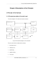
2.1.1.1Schematic diagram of the main board
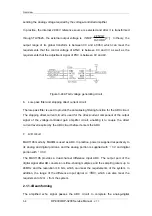
The main board can realize the functions such as transmission, reception, beamforming,
signal processing, DSC, Cine review, networking, USB, VIDEO, and VGA, etc.
The hardware of the main board supports an transmission circuit, which is divided into an
low-voltage transmission pulse drive circuit and 80-channel high-voltage transmission
pulse drive circuit. The transmission is realized by the EP1S10
(
FPGA of Stratix
series
)
, and its sequence is controlled by the FPGA as well.
The high voltage isolation and reception selection circuit is mainly used for the isolation
between the reception circuit and the high voltage generated by the transmission circuit.
The conversion among the elements and channels is directly executed by the high
voltage isolation circuit rather than the high voltage switch. Therefore the high voltage
isolation circuit also has the function of the reception selection circuit, and the control
signal of the reception selection circuit is provided by EP1S10.
The voltage-controlled gain amplifier circuit can realize the functions of low noise pre-
amplifier and voltage-controlled gain amplifier. The DP-3300/3200 does not fold the
reception channels. The A/D circuit is used for the analog-to-digital conversion of the
output of the voltage-controlled gain amplifier circuit. The output is connected to EP1S10,
and the low-pass filter before the A/D circuit is used for anti-aliasing filtering.
3-2
DP-3300/DP-3200
Service Manual
(
V1.1
)
Содержание DP-3200
Страница 1: ...DP 3300 DP 3200 Digital Ultrasonic Diagnostic Imaging System Service Manual...
Страница 2: ......
Страница 11: ...DP 3300 DP 3200 Service Manual V1 1 I...
Страница 12: ......
Страница 16: ......
Страница 20: ......
Страница 76: ......
Страница 81: ...P N 2302 20 34499 V 1 1...


