5
Mimo Monitors
Sales:
1-855-YES-MIMO (937-6466)
2
2
Power supply ON
Red then turn Green after kernel boot up.
Power supply OFF
LED light off.
Power on the Product
Step 1
Plug the power source into the AC/DC in jack (
#8
in
Product
Instruction
).
Step 2
Switch the power switch (
#15
) on the bottom of this product to
ON
.
Insert SD Card
This product supports external SD card. Please insert your SD card into the
SD Card Slot (
#2
in
Product Instruction
) on the top of this product.
Insert USB Devices
This product supports USB and Micro-USB to deal with your files.
USB
Plug your USB memory into the USB port (
#10
in
Product Instruction
) on
the bottom of this product, and then you can do the file operations via the File
Browser. (See in
Browse Files
).
Micro-USB
Connect the Micro-USB port (
#4
in
Product Instruction
) on the bottom of
this product and the USB port on your computer with a Micro-USB-to-USB
cable.
IR
Receiver:
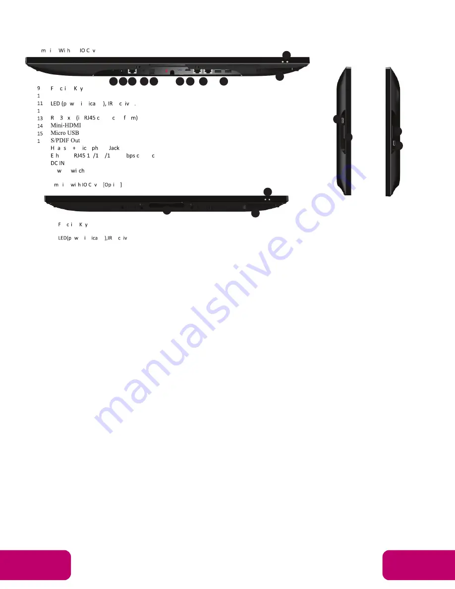
9.
USB Port x 2:
support USB 2.0 Host type A
10. RS232 Port x 2:
in RJ45 connector form
11. S/PDIF Port:
support S/PDIF audio output
12. H Microphone Jack
13. 10/100Mbps RJ45 Ethernet Port:
support Ethernet connection
14. Power Switch:
switch power ON/OFF
15. WiFi Receiver
un t on e .
Add-on Module Slot
o er nd tor re e er
USB 2.0
S2 2 2 n
onne tor or
0.
.
2.
.
e d et M ro one
.
t ernet
0 00 000 M
onne tor
.
6.
Po er S t
-
Botto S de t o er
t on
un t on e
Add-on Module Slot
o er nd tor
re e er.
-
e t S de
6.
Add-on Module Slot
8.
USB 2.0 Port
-
t S de
Mechanical Design Continued
20 19 18 17 16
15 14 13
12
9
11
11
10
9
2.
SA ount ole 00 00
.
S e er
.
o er
t on
.
un t on e .
6.
Add-on Module Slot
-
Botto S de t out o er
-
Botto S de t o er
t on
.
un t on e
6.
Add-on Module Slot
.
o er nd tor
re e er.
-
e t S de
6.
Add-on Module Slot
8.
USB 2.0 Port
-
t S de
6.
Add-on Module Slot
8.
USB 2.0 Port.
14
12
12
14
6.
Po er S t
-
Botto S de t o er
t on
-
t S de
.
17.
18.
19.
20.
9.
10.
11.
.
un t on e
6.
Add-on Module Slot
.
o er nd tor
re e er.
-
e t S de
12. Add-on Module Slot
14. USB 2.0 Port
.


