background image

© 2013 MIMAKI ENGINEERING CO.,LTD.

6.4.1

P.1

R.1.0

1

2

3

4

5

6

7

8

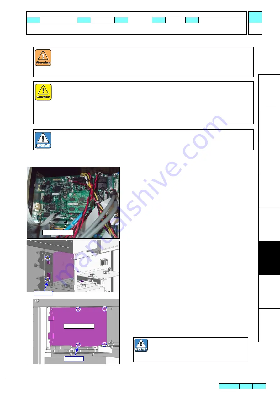
6.4.1 Main PCB assy.

Work procedures

1. Turn off the main power supply and remove the power plug 

from the main body.

2. Open the cover RRU, and disconnect all connector on the PCB.

3. Remove the screw, and remove the 

main PCB assy.

.

4. Change to mount the 

memory PCB

 onto the new main PCB.

5. Reverse the disassembly procedure for reassembly.

After turning off the sub and main power switches, unplug the power cord. Make sure to take 15 minutes
before restarting the operation. It is very dangerous if sleep mode functions mistakenly during the operation.
Moreover, the PCB may be damaged in case electric charge still remains inside.
Also, there is a possibility of electric shock because of high voltage applied to the high-power part of the DC
power supply assy. Take care to avoid contact with it.

A button type lithium battery is used for this board. Warn following 1)~4).

1), Danger of explosion if battery is incorrectly replaced.
2), Replace only with the same or equivalent type recommended by the manufacture.

Recommended type : [CR2032]

3), Dispose of used batteries according to the manufacturer

'

s instructions.

4),When the battery is replaced with a new one, pay attention to the polarity at replacing.

Proceed with the work after well confirmed the following processes in advance.

3.3.1 Replacement of the Main PCB assy.

Main PCB assy.

Screw(x2)

Screw(x4)

Main PCB assy.

When a used Main PCB is to be discarded, 
remove the installed battery (CR2032).
Disposal of the used battery according to manu-
facturer’s instructions

 MAINTENANCE MANUAL > Disassembly and Reassembly > Electrical Parts > Main PCB assy.

Model

SWJ-320S

Issued 2012.07.19 Revised

F/W ver

Remark

1.0

Rev.

Содержание SWJ-320 S2

Страница 1: ...MIMAKI ENGINEERING CO LTD URL http eng mimaki co jp Service Documents D500764 13 MAINTENANCE MANUAL ...

Страница 2: ...List was added Added 2 3 5 P 2 1 1 List was added Added 2 3 6 1 1 List was added Added 2 3 7 1 1 List was added Revised 3 3 2 1 1 Power supply is changed Added 4 2 1 1 1 Description in the outline was added numerical value in the work flow was changed Revised 4 2 4 1 1 Numerical value was changed Added 4 2 5 1 0 Added Added 4 2 6 1 0 Added Added 4 2 7 1 0 Added following section number was the ord...

Страница 3: ...rts replacement Ink charging Deleted Step 5 Corrected Photo of Step 6 and text Revised 4 2 11 P 3 1 1 After parts replacement Ink charging Deleted Step 5 Corrected Photo of Step 6 and text Revised 4 3 4 P 1 1 1 Corrected Illustration of Step 2 Added 4 3 7 1 0 Added Revised 6 1 1 P 2 1 1 Corrected Photo of Feeding take up left side cover Revised 6 3 2 P 1 1 1 Corrected Illustration of Step 2 Revise...

Страница 4: ...djustment 4 1 Operation Matrix 4 1 1 For Head adjustment jig 4 2 Adjustment Items 4 2 1 HEAD ADJUST 4 2 2 HEAD ADJUST Carriage base tilting 4 2 3 HEAD ADJUST Head tilting 4 2 4 HEAD ADJUST Stagger Forward backward 4 2 5 HEAD ADJUST SLANT ADJUST 4 2 6 HEAD ADJUST STAGGER ADJUST 4 2 7 HEAD ADJUST POSITION ADJUST 4 2 8 PRINT ADJUST 4 2 9 REPLACE COUNT 4 2 10 DEFAULT SET 4 2 11 CAPPING 4 2 12 ADJUST W...

Страница 5: ...ction Fan Relay 6 5 Sensors 6 5 1 Y origin Sensor 6 6 Pressurizing relations 6 6 1 Air Tank Sensor assy 6 6 2 Plural solenoid valve assy 6 6 3 Pressure pump assy 6 6 4 Pressure switch assy 6 6 5 Lighting LED assy 6 7 Repeated winding relations 6 7 1 Feeding Slack Sensor assy 6 7 2 Take up Slack Sensor assy 6 7 3 Feeding Motor assy 6 7 4 Take up Motor assy 6 7 5 Feeding Motor Relay 6 7 6 Take up Mo...

Страница 6: ... 2013 MIMAKI ENGINEERING CO LTD 1 2 3 4 5 6 7 8 1 Operating Principle 1 1 Basic Operation 1 2 Maintenance Function 1 3 InkSystem MAINTENANCE MANUAL Operating Principle Basic Operation ...

Страница 7: ... 2013 MIMAKI ENGINEERING CO LTD 1 2 3 4 5 6 7 8 MAINTENANCE MANUAL Basic Operation Maintenance Function Operating Principle 1 1 Basic Operation 1 2 Maintenance Function 1 3 InkSystem ...

Страница 8: ... 2013 MIMAKI ENGINEERING CO LTD 1 2 3 4 5 6 7 8 MAINTENANCE MANUAL Operating Principle InkSystem Operating Principle 1 1 Basic Operation 1 2 Maintenance Function 1 3 InkSystem ...

Страница 9: ... 1 Configuration Ink Supply Path Diagrammatic Illustration The ink supplying routes are shown below Ink bottle Pump Filter Ink tank Print head MAINTENANCE MANUAL Operating Principle InkSystem Configuration Model SWJ 320S Issued 2012 07 19 Revised F W ver Remark 1 0 Rev ...

Страница 10: ... 2013 MIMAKI ENGINEERING CO LTD 1 2 3 4 5 6 7 8 2 Electrical Parts 2 1 Block Diagram 2 2 Operation Explanation 2 3 Circuit Board Specifications MAINTENANCE MANUAL Electrical Parts Block Diagram ...

Страница 11: ... HTC2 INLET1 L N E L N E L N E L N E SW5 E106926 E106738 CN21 1 5 CN17 1 5 CN18 1 5 SNS 1 5 SNS 1 5 SNS 1 5 SNS 1 5 CN 1 4 CN 1 68 CN 1 68 CN 1 68 CN 1 68 CN2 1 5 CN5 1 5 CN1 1 5 CN14 1 5 CN28 1 5 CN24 1 5 CN25 1 5 CN26 1 5 CN27 1 5 CN23 1 5 CN22 1 5 CN20 1 5 CN19 1 5 CN3 1 5 CN6 1 5 CN9 1 5 CN11 1 5 CN10 1 5 CN12 1 5 CN16 1 5 CN3 1 8 CN2 1 14 CN7 1 5 500W SW6 FL1 EMI filter Light3 LFA15F 5 GJ1 E0...

Страница 12: ...itch3 Switch AC Motor VAL Switch4 SW10 SENS OJ 6505 N2 Light1 INLET3 E300513 E300513 Ink pump3 Switch E300588 VAL4 SW12 SENS OJ 6505 N2 SENS4 OJ 6505 N2 F HEAD GEN5 E105719 Switch Switch SW3 Switch AC Motor E300513 Switch E SW R Switch Purge Motor Volume SW9 Ink pump4 VAL1 VAL3 F3 FUSE STM1 STM2 STM5 STM3 STM4 DC Motor Pressurization Valve Valve Valve Valve Switch Valve Switch Valve Switch Relay A...

Страница 13: ... 2013 MIMAKI ENGINEERING CO LTD 1 2 3 4 5 6 7 8 MAINTENANCE MANUAL Electrical Parts Operation Explanation Electrical Parts 2 1 Block Diagram 2 2 Operation Explanation 2 3 Circuit Board Specifications ...

Страница 14: ...013 MIMAKI ENGINEERING CO LTD 1 2 3 4 5 6 7 8 MAINTENANCE MANUAL Electrical Parts Circuit Board Specifications Electrical Parts 2 1 Block Diagram 2 2 Operation Explanation 2 3 Circuit Board Specifications ...

Страница 15: ...When installing the new power supply PLA600F 36 R to the model that uses the old power supply PBA600F 36 R change the specs of above No 1 to 7 to the same as those of PLA600F 36 R DC power supply type name Applicable models OLD PBA600F 36 G SWJ 320S2 M031E120 SWJ 320S4 M131E524 NEW PLA600F 36 R SWJ 320S2 M031E121 SWJ 320S4 M131E525 No Type Name DC power supply OLD PBA600F 36 G NEW PLA600F 36 R 1 M...

Страница 16: ...m Terminal block Pin No Terminal name Function Connected to Remarks 1 L AC Line input Noise Filter 2 N AC Nutral input Noise Filter 3 FG FG 4 V 0V EPL Main PCB assy CN11 5 V 0V 6 V DC37V EPL Main PCB assy CN11 7 V DC37V Parts No Pin Connected to Connecting desti nation CN Remarks CN1 10 EPL Main PCB assy CN12 CN2 10 EPL Main PCB assy CN12 CN3 8 EPL Main PCB assy CN12 MAINTENANCE MANUAL Electrical ...

Страница 17: ... 1 L AC Line input Noise Filter 2 N AC Nutral input Noise Filter 3 FG FG 4 V 0V EPL Main PCB assy CN11 5 V 0V 6 V DC37V EPL Main PCB assy CN11 7 V DC37V Parts No Pin Connected to Connecting desti nation CN Remarks CN1 10 EPL Main PCB assy CN12 POW_CN1 POW_CN2 and PW_CN3 of DC POW cable 320Assy is not connected DC POW cable 320assy is two CN1 connectors Connector which is written LC POW CN1 is conn...

Страница 18: ...r that has PBA600F 36 G SWJ 320S2 M031E120 SWJ 320S4 M131E524 Parts No Pin Connected to Connecting desti nation CN Remarks CN1 4 Host PC USB2 0 I F CN2 14 Not use UART x 2CH CN3 80 Debug board For Debug CN4 9 Not use JTAG I F For CPLD writing or FPGA JTAG TEST CN5 80 DDRII PRAM PCB assy For Memory PCB CN6 30 FFC Changes PCB assy CN1 Head IO signal CN7 20 Optical conversion PCB assy CN1 CN8 12 Opti...

Страница 19: ...r CN16 5 Not use Parts No Signal Remarks TP16 19 GND Parts No Rate Using Voltage Remark F1 6 3A AC125V DC60V 37V 36V CN6 First system F2 6 3A AC125V DC60V 37V 36V CN6 Second system F3 6 3A AC125V DC60V 37V 36V CN8 Second system F4 6 3A AC125V DC60V 37V 36V CN9 F5 6 3A AC125V DC60V 37V 36V CN8 Second system F6 3 15A AC125V DC60V 5V 36V CN9 Parts No Check points Condition for lighting D2 3 3V F W CP...

Страница 20: ...et connect It is blinking when it is connected yellow LED and LAN cable and it is sending and receiving the data D33 3 3V Ethernet connect It is light on when it is connected green LED and LAN cable D34 3 3V Ethernet connect It is light on when it is connected to the network devices which is full duplex D35 5V Power supply check 5V CN11 5pins current is on 1 D36 37V Power supply check 37V CN11 2pi...

Страница 21: ...Remark 1 0 Rev 2 3 3 DC Power Supply DC5V Outline Unit name Switching power supply LFA15F 5 J1 Mounted position Electrical box Main specifications Power supply for backup circuit DC5V List of Connectors For the details of connecting destinations refer to the block diagram Parts No Pin Connected to Connecting desti nation CN Remarks CN1 5 Noise Filter AC input CN2 2 EPL Main PCB assy CN11 DC output...

Страница 22: ...inations refer to the block diagram Parts No Pin Connected to Connecting desti nation CN Remarks CN1 10 Not use Spare CN2 10 Not use Connector is not mounted CN3 20 EPL Main PCB assy CN9 CN4 3 Stop switch CN5 16 Not use Spare CN6 16 Not use Spare CN7 9 Not use For Debug CN8 8 Ink pressurizing part Suction fan CN9 30 Wiper sensor X axis origin sensor Y origin sensor Feeding slack sensor CN10 12 Suc...

Страница 23: ...nsor check Not used Not light on D13 5V CN9 sensor check Wiper sensor light on when sensor is on light off when sensor is off D14 5V Keyboard check Not used Not light on D15 5V CN9 sensor check Not used Not light on D21 5V CN9 sensor check Y origin sensor light on darkly when sensor is on light on brightly when sensor is off D22 5V CN9 sensor check Not used It is always light on darkly D23 5V CN9 ...

Страница 24: ...ssy CN2 Optical conversion PCB assy CN2 HDC PCB assy R CN1 HDC PCB assy L CN1 5 For the S2 model unused CN2 30 FFC Changes PCB assy CN1 HDC PCB assy L CN3 CN3 30 HDC PCB assy R CN2 Not use For the S2 model unused CN4 3 Not use Not use CN5 12 Optical conversion PCB assy CN2 HDC PCB assy L CN6 For the S2 model unused HDC PCB assy R CN1 CN6 12 HDC PCB assy R CN5 Not use For the S2 model unused CN7 6 ...

Страница 25: ...pare Parts No Check points Condition for lighting LED1 37V F1 check CN3 Huse1 37V and FPGA is normal LED2 3 3V CPL It is light on when CPLD is completed to write down LED3 37V F2 check CN15 Huse2 37V and FPGA is normal LED4 3 3V FPGA It is light off when FPGA is FIFO under LED5 5V CN16 sensor check Not used Not light on LED6 3 3V FPGA It is light off when FPGA is over through rate of wave shape LE...

Страница 26: ...cifications Has LCD with 2 lines of 20 characters and key switches List of Connectors For the details of connecting destinations refer to the block diagram Test point LED light on Parts No Pin Connected to Connecting destina tion CN Remarks CN1 10 EPL Main PCB assy CN10 CN2 16 LCD CN3 2 Not use CN4 9 Not use CN5 4 Remote switch assy Parts No Signal Remarks TP1 GND Parts No Check points Condition f...

Страница 27: ... Additionally the PCB relays to supply the power DC37V to the HDC PCB List of Connectors Electrical box side Carriage side For the details of connecting destinations refer to the block diagram LED light on Parts No Pin Connected to Connecting destination CN Remarks CN1 5 Main PCB assy CN7 CN2 12 Optical conversion PCB assy CN3 CN3 12 Main PCB assy CN8 U1 2 Optical conversion PCB assy U1 Parts No P...

Страница 28: ...B The PCB is placed within the electrical box and on the carriage and converts the FFC to the cable for the cable bear List of Connectors Electrical box side Carriage side For the details of connecting destinations refer to the block diagram Parts No Pin Connected to Connecting destination CN Remarks CN1 30 EPL Main PCB assy CN6 Connector for FFC CN2 14 FFC Changes PCB assy CN2 CN3 3 CN4 6 CN5 10 ...

Страница 29: ...PRAM 1GB PCB assy Model SWJ 320S Issued 2012 07 19 Revised F W ver Remark 1 0 Rev 2 3 9 DDRII PRAM 1GB PCB assy Outline Unit name DDRII PRAM 1GB PCB assy List of Connectors For the details of connecting destinations refer to the block diagram Parts No Pin Connected to Connecting desti nation CN Remarks CN1 80 EPL Main PCB assy CN5 CN1 ...

Страница 30: ...0S Issued 2012 07 19 Revised F W ver Remark 1 0 Rev 2 3 10 ID Contact PCB CN032 Simple assy Outline Unit name ID Contact PCB CN032 Simple assy Main specifications The ink ID is read out by this PCB List of Connectors For the details of connecting destinations refer to the block diagram Parts No Pin Connected to Connecting desti nation CN Remarks CN1 80 EPL Main PCB assy CN5 ...

Страница 31: ... 2013 MIMAKI ENGINEERING CO LTD 1 2 3 4 5 6 7 8 MAINTENANCE MANUAL Workflow Ink Related Parts 3 Workflow 3 1 Ink Related Parts 3 2 Driving Parts 3 3 Electrical Parts ...

Страница 32: ... power comes ON due to the sleep control if turned to OFF by the power SW on the panel Covers 3 Removal of covers etc Remove the carriage cover 6 1 1 Printing Head 4 Head replacement 6 2 2 Ink charging 5 Power ON Turning the power ON to start the machine 6 Head ink charging Executing the INK PURGE Feed pump ON to charge the ink to the head 4 2 14 7 Test printing Checking the nozzle condition Adjus...

Страница 33: ... turn the main power OFF since the power comes ON due to the sleep control if turned to OFF by the power SW on the panel Covers 3 Removal of covers etc Remove the carriage cover 6 1 1 Ink tank 4 Ink tank replacement On the left back side of machine replacing the ink tank 6 2 1 Ink charging 5 Power ON Turning the power ON to start the machine 6 Head ink charging Executing the INK PURGE Feed pump ON...

Страница 34: ...is disconnected from the ink bottle 4 2 14 2 Power OFF Turning the main power OFF Be sure to turn the main power OFF since the power comes ON due to the sleep control if turned to OFF by the power SW on the panel Ink Supply Pump 3 Ink Supply Pump replacement 6 2 3 Ink charging 4 Power ON Turning the power ON to start the machine 5 Head ink charging Executing the INK PURGE Feed pump ON to charge th...

Страница 35: ... 2013 MIMAKI ENGINEERING CO LTD 1 2 3 4 5 6 7 8 MAINTENANCE MANUAL Workflow Driving Parts Workflow 3 1 Ink Related Parts 3 2 Driving Parts 3 3 Electrical Parts ...

Страница 36: ...ration Description Ref Power OFF 1 Power OFF Turning the main power OFF Be sure to turn the main power OFF since the power comes ON due to the sleep control if turned to OFF by the power SW on the panel X axis Motor 2 X axis motor replacement 6 3 1 Adjustment 3 Adjustment of the belt tension Adjusting the tension of X drive belt 4 3 3 For the power OFF be sure to turn the main power OFF If the sle...

Страница 37: ...operation Description Ref Power OFF 1 Power OFF Turning the main power OFF Be sure to turn the main power OFF since the power comes ON due to the sleep control if turned to OFF by the power SW on the panel Y axis Motor 2 Y axis motor replacement 6 3 2 Adjustment 3 Adjustment of the belt tension Adjusting the tension of Y drive belt For the power OFF be sure to turn the main power OFF If the sleep ...

Страница 38: ... 2013 MIMAKI ENGINEERING CO LTD 1 2 3 4 5 6 7 8 MAINTENANCE MANUAL Workflow Electrical Parts Workflow 3 1 Ink Related Parts 3 2 Driving Parts 3 3 Electrical Parts ...

Страница 39: ... during the operation Moreover the PCB may be damaged in case electric charge still remains inside Also there is a possibility of electric shock because of high power voltage applied to the high pres sure part of the DC power supply unit Take care to avoid contact with it If it is impossible to upload the parameters conduct Parameter Draw to note the setting values Then manually register the value...

Страница 40: ...stakenly during the operation Moreover the PCB may be damaged in case electric charge still remains inside Also there is a possibility of electric shock because of high power voltage applied to the high pres sure part of the DC power supply unit Take care to avoid contact with it Item Work operation Description Ref Power OFF 1 Power OFF Power cable removing from main body Turing the main power OFF...

Страница 41: ...akenly during the operation Moreover the PCB may be damaged in case electric charge still remains inside Also there is a possibility of electric shock because of high power voltage applied to the high pres sure part of the DC power supply unit Take care to avoid contact with it Item Work operation Description Ref Power OFF 1 Power OFF Power cable removing from main body Turing the main power OFF a...

Страница 42: ...unctions mistakenly during the operation Moreover the PCB may be damaged in case electric charge still remains inside Also there is a possibility of electric shock because of high power voltage applied to the high pres sure part of the DC power supply unit Take care to avoid contact with it Item Work operation Description Ref Power OFF 1 Power OFF Power cable removing from main body Turing the mai...

Страница 43: ...ts parameter to the PC Power OFF 2 Power OFF Power cable removing from main body Turing the main power OFF and then removing the power cable from the main body PCB replacement 3 Central IO PCB assy replacement 6 4 6 Machine start up 4 Connecting the power cable Connecting the power cable to the main body 5 Starting up in the system parame ter input mode Turning the power switch ON and starting up ...

Страница 44: ...f turned to OFF by the power SW on the panel 2 Removal of covers etc Remove the following covers Carriage cover SD PCB cover 6 1 1 Encoder Sen sor 3 Encoder Sensor replacement 6 4 4 Check Adjustment 4 Encoder position adjustment Checking the encoder mounting at the specified position 4 3 6 5 Power ON Turning the power ON to start the machine 6 Encoder check Carry out the encoder check to confirm i...

Страница 45: ... 2013 MIMAKI ENGINEERING CO LTD 1 2 3 4 5 6 7 8 MAINTENANCE MANUAL Adjustment Operation Matrix 4 Adjustment 4 1 Operation Matrix 4 2 Adjustment Items 4 3 Mechanical Adjustment ...

Страница 46: ...cedure 1 Store the tip of adjustment bar into the main body by rotating the tilt adjustment screw and the forward backward position adjustment screw counterclockwise 2 Attach the head adjustment jig to the head Tilt adjust ment bar Tilt adjustment screw Forward back ward position adjustment bar Forward backward position adjust ment screw Name Rotating direction Function Forward backward position a...

Страница 47: ... adjustment screw and tilt adjustment screw clockwise and push out the adjustment bars Separate this section and the jig 2 mm Tighten the screws Near side Push out the forward backward position adjustment bar Push out the tilt adjustment bar MAINTENANCE MANUAL Adjustment Operation Matrix For Head adjustment jig Model SWJ 320S Issued 2012 07 19 Revised F W ver Remark 1 0 Rev ...

Страница 48: ... 2013 MIMAKI ENGINEERING CO LTD 1 2 3 4 5 6 7 8 MAINTENANCE MANUAL Adjustment Adjustment Items 4 Adjustment 4 1 Operation Matrix 4 2 Adjustment Items 4 3 Mechanical Adjustment ...

Страница 49: ...y SLANT ADJUST Disadvantages Image quality is deteriorated in Uni d printing rather than adjusting slant by SLANT ADJUST 2 Adjust slant stagger and position separately by SLANT ADJUST STAGGER ADJUST POSI TION ADJUST Advantages Image quality is better in Uni d printing compared to adjusting slant with AVERAGING ADJ Disadvantages In SLANT ADJUST maladjustment may occur by the effect of media skew Sl...

Страница 50: ...cceptable range Nozzle check Dot missing or blurred Test Print To PRINT ADJUST 4 2 8 Head cleaning NG OK All heads NG Stagger Forward backward position NG Tilt Yes No To Head tilting adjustment 4 2 3 To Stagger Front and back adjustment 4 2 4 Head adjustment acceptable range Displacement amount on averaged adjustment patterns Head tilt Within 0 10um Stagger Front and back Within 0 10um MAINTENANCE...

Страница 51: ...ected turn the power off before reconnecting the connector If the ink supply port at the near side of the head is shaken the meniscus will be damaged When touching the port do not let it shake If the cap is kept off for a long time it may result in a skewed ink discharge trajectory or nozzle mis alignment If skewed ink discharge trajectory or nozzle misalignment occurs the head cannot be adjusted ...

Страница 52: ...ad4 Head1 Head2 For SWJ 320S2 Head4 Head1 Head3 Head2 Head1 Head2 Head number For SWJ 320S4 For SWJ 320S2 Forward backward position adjustment pattern Tilt adjustment pattern Stagger forward backward position Forward backward position adjustment pattern Tilt adjustment pattern MAINTENANCE MANUAL Adjustment Adjustment Items HEAD ADJUST Model SWJ 320S Issued 2012 07 19 Revised F W ver 2 20 Remark 1 ...

Страница 53: ...ace The head unit is possible to tilt in the right direction but not possible in the left direction since it is in the condition that the head unit is pressed to the right side This adjustment is performed when the head unit is required to be tilted in the left direction due to the accuracy vari ation of head unit The tilting of all head units are adjustable by tilting the carriage base to the lef...

Страница 54: ...PRINTING Within 10 μm Patern of Slant adjust AVERAGING ADJ The distance between the center of 2 broken lines and the line center should be within 10 μm Head condi tion Figure when viewed with a scope Adjustment No adjustment required If out of accept able range adjust the tilt ing of Carriage base If out of accept able range adjust the tilt ing of Head unit Not tilted Tilted to the right Tilted to...

Страница 55: ...of movement per one screw rotation Approx 50 µm The amount of front and back movement of pattern line Carriage base moving direction Screw clockwise Tilting right Screw counter clockwise Tilting left 7 Fix the carriage base screw loosened 8 Repeat the above procedure 3 to 7 until the tilting is within the acceptable range Adjustment screw MAINTENANCE MANUAL Adjustment Adjustment Items HEAD ADJUST ...

Страница 56: ...djusted properly After adjusting the tilt be sure to verify the stagger forward backward position ADJUST HEAD ADJUST ENT HEAD ADJUST AVERAGING ADJ ENT AVERAGING ADJ PRINT ENT AVERAGING ADJ PRINTING Patern of Slant adjust AVERAGING ADJ Within 10 μm The distance between the center of 2 broken lines and the line center should be within 10 μm Head fixing screw Tilt adjustment screw Head adjustment jig...

Страница 57: ...Adjustmentmethod tilt adjustment screw rotation direction Not tilted Tilted to the right Back side Near side Tilted to the left Back side Near side If the cap is kept off for a long time it may result in a skewed ink discharge trajectory or nozzle misalignment If skewed ink discharge trajectory or nozzle misalignment occurs the head cannot be adjusted properly so do not keep the cap off for a long...

Страница 58: ...ion adjustment After adjusting the stagger forward backward position be sure to verify the tilt ADJUST HEAD ADJUST ENT HEAD ADJUST AVERAGING ADJ ENT AVERAGING ADJ PRINT ENT AVERAGING ADJ PRINTING Within 10 μm Pattern for Stagger Front and back position adjustment AVERAGING ADJ The distance between the reference line center and the adjustment line center should be within 10μm Blue line reference he...

Страница 59: ...ard adjustment screw rotation direction Proper condition Blue line reference head Black line adjustment head When the stagger interval is wide When the stagger interval is narrow Back side Near side Back side Near side If the cap is kept off for a long time it may result in a skewed ink discharge trajectory or nozzle misalignment If skewed ink discharge trajectory or nozzle misalignment occurs the...

Страница 60: ...ST Outline of the head slant adjustment A B C D Head1 A B C D Head2 A B C D Head3 A B C D Head4 HEAD line1 HEAD line2 Tolerable range 30μm Bad Good Adjust so that the dots align in the tolerable range A B C D A B C D 320 nozzles Enlarged view Nozzles used for the check X direction 600 dpi 150 dpi C line on the both head is used 300 dpi 300 dpi Slant adjustment pattern Head configuration X directio...

Страница 61: ...ern Slant adjustment procedure 1 Confirm whether quantity of biggest gap by each scan is settled 30 μm If there is a head whose gap is out of the standard carry out the following adjustment LOCAL width 1000mm FUNCTION ADJUST ENT ADJUST HEAD ADJUST ENT FUNCTION HEAD ADJUST SLANT ADJUST ENT SLANT ADJUST PRINT START ENT Do not perform this adjustment with the carriage located on the Station Assy cap ...

Страница 62: ...s leaned to left turn it clockwise When the head has leaned to right turn it counterclockwise 5 Print the pattern again and examine it 6 When finished tighten the two screws to secure the head 7 Remove the two screws fixing the Head adjust tool and remove the tool Do not remove Head Head adjust tool Adjustment screw Head Repeat the adjustment and check with the pattern until the dots align in the ...

Страница 63: ...F W ver 2 20 Remark 1 0 Rev 4 2 6 HEAD ADJUST STAGGER ADJUST Overview of the Head Stagger adjustment Head Align each head of the Headline2 with the head of the Headline1 like this Headline1 Headline2 Base head Good pattern Wrong pattern Gap Overlap Base head Adjust the head stagger after check that no nozzle missing or trajectory for 4 nozzles lined up back and forth of the head ...

Страница 64: ...erns overlap by 4 dots width Check the same thing for the Headline2 and Headline3 patterns If the overlapped width is improper go to Head stagger adjustment procedure Tolerable range 0 10 μm LOCAL width 1000mm FUNCTION ADJUST ENT ADJUST HEAD ADJUST ENT FUNCTION HEAD ADJUST STAGGER ADJUST ENT STAGGER ADJUST PRINT START ENT Do not perform this adjustment with the carriage located on the Station Assy...

Страница 65: ...emove the tool Do not remove Head Head adjust tool Adjustment screw Head One turn of the adjustment screw moves the head approximately 500 μm In which direction to turn the screw Clockwise moves the head backward Counterclockwise moves the head forward Repeat the adjustment and check with the pattern until the interval becomes the standard value Tolerable range 0 10 μm When finished perform the he...

Страница 66: ...el SWJ 320S Issued 2013 03 08 Revised F W ver 2 20 Remark 1 0 Rev 4 2 7 HEAD ADJUST POSITION ADJUST Head position adjustment pattern C C AB D A B D Enlarged view with a magnifying glass Bad Good head1 head2 10 dots interval Tolerable range 0 10 μm 300mm Head3 C line Blue Head4 C line Black Enlarged view with a magnifying glass 4 color printer ...

Страница 67: ...t procedure Head position adjustment procedure 1 Loosen the two screws fixing the head to be adjusted 2 Install the Head adjust tool to the head with the two screws LOCAL width 1000mm FUNCTION ADJUST ENT ADJUST HEAD ADJUST ENT FUNCTION HEAD ADJUST POSITION ADJUST ENT POSITION ADJUST PRINT START ENT Do not perform this adjustment with the carriage located on the Station Assy cap Make sure to take c...

Страница 68: ... the screw Clockwise moves the head backward Counterclockwise moves the head forward Repeat the adjustment and check with the pattern until the dots align in the tolerable range Tolerable range 0 10 μm After the head position adjustment perform the head slant adjustment and position adjustment again and repeat them alternately until the both needs no more adjustment The head unit sometimes does no...

Страница 69: ...iDir PRINT ADJUST SiDir PRINT PRINT ADJUST PRINTING 720std SiDir WF1 H1A H1B 0 0 540Std 720Hi 1080Std BASIS SET 720std ReDir BiDir 99 9 99 9 PRINT ADJUST H1A H1C H1A H1D H1A H2A H1A H2D Due to the differences in distance between platen and heads the adjustment position of the refer ence lines may vary depending on the location Be sure to verify all patterns and enter correction values so that the ...

Страница 70: ...orrection value in the positive direction Reference lines Adjustment lines Enter a correction value in the negative direction Reference lines Adjustment lines PRINT ADJUST BASIS SET 720std The values set using BASIS SET are values cal culated as a guideline for correction values Thus the actual ink landing position may be mis aligned Be sure to adjust the landing position for each mode that will b...

Страница 71: ...Select ADJUST REPLACE COUNT 2 Select the item to be indicated and then fix it by ENTER to indicate it Switch ENTER Finalizes to Information indicating display END Return No Item Remarks 1 SCAN COUNT Number of scans 2 USE TIME Time of Power ON Unit H 3 WIPING COUNT Number of wiping 4 DRAW LENGTH Drawing length m 5 DRAW AREA Drawing area m2 6 PUMP MOTOR Rotation time of each pump motor Unit H FUNCTI...

Страница 72: ...question 2 SHIPPING set Initializing parameters of others than the adjustments 3 MAINTE PARAMETER Initialize the parameter in question 4 SERVO PARAMETER Initialize the parameter in question 5 FEED PARAMETER Initialize the parameter in question 6 HEAD PARAMETER Initialize the parameter in question 7 OPE PARAMETER Initialize the parameter in question 8 INK PARAMETER 1 Initialize the parameter in que...

Страница 73: ...sition 1 From the position where the heads and caps are separated press the key 2 The back side of the caps will come into contact with the heads first From that position continue pressing the key Stop at the position where among all of the heads at least one of them comes into contact with the front side of a cap 3 From the position where the front side of a cap comes into contact with a head pre...

Страница 74: ...ust barely in contact 2 Once the carriage and station are in contact press the key 5 times Shift 0 5 to the left Move cap adjust ENTER Set CAPPING FLUSHING POS 2 0 Barely in contact position Shift 0 5 to the left from contact position Approximately 0 5 mm 20 0 20 0 MAINTENANCE MANUAL Adjustment Adjustment Items CAPPING Model SWJ 320S Issued 2012 07 19 Revised F W ver 1 0 Remark 1 0 Rev ...

Страница 75: ...ts the wiper position The adjusted value is stored in the system parameter Work Procedures 1 Select ADJUST ADJUST WIPER 2 Confirm and adjust the center position of the head and the wiper nozzle Horizontally shifts the head ENTER Finalizes and end END End 3 After adjustment register with the ENTER key and then ter minate the operation FUNCTION ADJUST ENT ADJUST ADJUST WIPER ENT ADJUST WIPER WIPER P...

Страница 76: ...ter completing to clean ENTER To next 4 Set the wash bottle and press the ENTER key When washing can not be completed below message is dis played on the screen R e t r y 5 Check the sub tank state and select the key Retry washing To next FUNCTION ADJUST ENT ADJUST HEAD WASH ENT WIPER CLEANING COMPLETED ENT SET WASH BOTTLE COMPLETED ENT WASHING PLEASE WAIT You must set all channels to cleaning bott...

Страница 77: ... PORT WASHING START ENT Carriage moves to Left maintenance position Ink discharge tray Air purge jig Set so that the tips of the air purge jig come into contact with the bottom of the discharge tray Counter flow of the washing liquid and inflow of the air may be occurred Purge the air and then discharge the washing liquid from the tip of the jig by pressing the purge button and then end after it i...

Страница 78: ...ccording the referenced procedure Work Procedures 1 Select ADJUST INK PURGE 2 Press ENTER key to move the carriage to the maintenance position 3 Select ON OFF of the ink pump ON The ink pump operates until the float sensor within the ink tank turns ON OFF The ink pump does not operate Liquid supply pump ON OFF selection ENTER End 4 Check the ink color and press the purge button 5 Manually perform ...

Страница 79: ...p ON Liquid supply pump ON OFF selection ENTER End 5 Insert the air purge jig into the ink port and insert another end of the jig for discharge into the waste ink tank or tray and press the purge button Press the button continuous until ink is discharged flow from end of the jig 6 Manually perform wiping 7 Press ENTER key to end FUNCTION ADJUST ENT ADJUST INK PURGE ENT INK PURGE CARRIAGE OUT ENT I...

Страница 80: ...n 4 Turn the ink pump ON Liquid supply pump ON OFF selection ENTER End 5 Insert the air purge jig into the ink port and insert another end of the jig for discharge into the waste ink tank or tray and press the purge button Press the button continuous until ink is discharged flow from end of the jig 6 Manually perform wiping 7 Press ENTER key to end FUNCTION ADJUST ENT ADJUST INK PURGE ENT INK PURG...

Страница 81: ...d 2012 07 19 Revised F W ver 1 0 Remark 1 0 Rev 4 2 15 HEAD ID Outline HEAD ID represents each head characteristic written at shipping The variation between heads is unified by inputting the value to printer As this machine reads the head ID from the mounted memory ROM on the print head at each startup it is not necessary to set the head ID ...

Страница 82: ... W ver 1 0 Remark 1 0 Rev 4 2 16 Serial No Outline Confirming and changing of the serial No of SWJ 320S Work Procedures 1 Select ADJUST SERIAL No 2 Confirm the serial No or change it To move Cursor To change Value ENTER Confirms END Return Normally don t change the serial No which has been registered FUNCTION ADJUST ENT ADJUST SERIAL No ENT SERIAL No S N 00000000 ...

Страница 83: ... DEALER No Outline Check and set the dealer No For dealer No 8 digit alphameric characters 0 to 9 A to Z can be input Procedures 1 Select ADJUST DEALER No 2 Input check the dealer No Changing value Moving cursor When the cursor is at the right end or the left end even if the key is pressed it does not move ENTER Confirmation END Cancel FUNCTION ADJUST ENT ADJUST DEALER No DEALER No D N 10000000 ...

Страница 84: ...ing amount of media Provides a baseline value for user compensation value Adjust this when the parameter is initialized By this adjustment the user compensation value is cleared Pattern0 1 2 3 4 5 6 7 8 9 10 11 12 13 14 15 DECENTERING pattern FEED COMP pattern LOCAL WIDTH 1000mm MEDIA SET MEDIA RESET ENT FUNCTION ADJUST ENT ADJUST FEED COMP 2 ENT When the media is changed re set the width of media...

Страница 85: ...o direction due to insufficient adjustment value Pattern0 0 250 250 OK NG More distant than 40μm NG Due to a lot of adjustment values reduce adjustment values If the value of pattern 0 exceeds 30 check if the front and back of media does not touch to the floor and print the adjusting pattern again If the pattern is within 40 µm the adjustment is not required Pattern1 0 Pattern15 0 MAINTENANCE MANU...

Страница 86: ...JUST FEED COMP 2 ENT When the media is changed re set the width of media and the height of head in MEDIA SET DECENTERING FEED COMP 2 FEED COMP ENT Set the drawing origin as follows Set in LOCAL ORIGIN X 0 Y 0 When the media is changed re set MEDIA WIDTH and HEAD HEIGHT FEED COMP PRINT ENT Pattern drawing FEED COMP PRINT A pattern having width of media is drawn Compensation value is too large Compe...

Страница 87: ...sor To change Value ENTER Confirms Return FUNCTION ADJUST ENT ADJUST LAN CONFIG ENT LAN IP ADDRESS ENT LAN IP ADDR DDD DDD DDD DDD 0 255 LAN DEFAULT GATEWAY ENT LAN DEF G W DDD DDD DDD DDD 0 255 LAN DNS ADDRESS ENT LAN DNS DDD DDD DDD DDD 0 255 LAN SUB NET MSK ENT LAN NET MASK 31 8 31 LAN SMTP ADDRESS ENT LAN SMTP wiztec co jp LAN POP3 ADDRESS ENT LAN POP3 wiztec co jp LAN USER NAME ENT LAN USER N...

Страница 88: ...nt Items Time Set Model SWJ 320S Issued 2012 07 19 Revised F W ver 1 0 Remark 1 0 Rev 4 2 20 Time Set Outline Setting the time Procedures 1 Select ADJUST TIME SET 2 Set the time Changing item Changing value ENTER Confirmation END Cancel FUNCTION ADJUST ENT ADJUST TIME SET ENT TIME SET 2011 10 05 21 36 00 ...

Страница 89: ...INTENANCE MANUAL Adjustment Adjustment Items Nozzle Recovery Model SWJ 320S Issued 2012 07 19 Revised F W ver 1 0 Remark 1 0 Rev 4 2 21 Nozzle Recovery Outline Set NOZZLE RECOVERY The same function as MAINTENANCE NOZZLE RECOVERY Registrable up to 16 pcs per nozzle line ...

Страница 90: ...SB breakage as you cannot upload parameters charge ink information is discarded Therefore it is necessary to back up charge ink information 2 When replacing ink it is necessary to save charge ink information of old ink type into the IC chip 1 Select ADJUST CHARGE INK 2 Select INK IC BACKUP FUNCTION ADJUST ENT ADJUST CHARGE INK ENT CHARGE INK INFORMATION ENT COL K CS100 1234cc LIMIT 2012 09 After w...

Страница 91: ...cc you cannot write it into the IC If charge ink information of all colors are less than 1cc NONE is displayed Only one type color can be written into one ink IC When you write charge ink information of four colors prepare four ink ICs PLEASE INSERT INK IC WRONG INK IC CANNOT WRITE UNUSED INK IC CANNOT WRITE You can write only into the ink IC usable for SWJ 320S series If you set the ink IC other ...

Страница 92: ...on inside the main body is cleared and writing to the memory starts 6 Press ENTER CHARGE INK CLEAR ENT SELECT COLOR BLACK SELECT COLOR NONE If the charge ink information registered in the main body is less than 1cc it is not displayed for SELECT COLOR If charge ink information of all colors are less than 1cc NONE is displayed CLEAR OK NO YES WRITING DO NOT REMOVE INK IC COMPLETED ENT Do not turn o...

Страница 93: ...re as follows OLD PBA600F 36 G SWJ 320S2 M031E120 SWJ 320S4 M131E524 NEW PLA600F 36 R SWJ 320S2 M031E121 SWJ 320S4 M131E525 If the power source PBA600F 36 G or PLA600F 36 R or the main PCB is replaced monitor the following measur ing positions with a tester and adjust the voltage to 37V with the adjusting volume on the power side Adjusting voltage 36 26 37 74V Measuring positions 1 pin and 3 pin o...

Страница 94: ...7V R 1 1 1 2 3 4 5 6 7 8 1 pin 3 pin Main PCB Power supply PLA600F 36 R CN11 Adjusting volume New Power supply PLA600F 36 R MAINTENANCE MANUAL Adjustment Adjustment Items Power voltage adjustment DC37V Model SWJ 320S Issued 2012 07 19 Revised 2013 08 28 F W ver 1 0 Remark 1 1 Rev ...

Страница 95: ...Turn the power ON 2 Shift in the setting mode by pressing SET and for more than 3 seconds simultaneously 3 Set 0000 to 0001 by pressing 4 Press SET 5 Set it to 0070 Upper limit temperature by pressing v and 6 Press SET 7 End the setting mode by pressing SET and for 3 seconds simultaneously Checking of setting 1 Check that the initial indication is 70 at shipment 400 by switching the power switch o...

Страница 96: ... 2013 MIMAKI ENGINEERING CO LTD 1 2 3 4 5 6 7 8 MAINTENANCE MANUAL Adjustment Mechanical Adjustment 4 Adjustment 4 1 Operation Matrix 4 2 Adjustment Items 4 3 Mechanical Adjustment ...

Страница 97: ...ified value 3 1mm at the front side of cap In case of out of the specification perform the following adjust ment continuously 5 Loosen the fixing screws 4 and adjust the height with the adjustment screws Fixing screw 4 P4x12SMW Adjustment screw 4 CS4x18 hexagon socket head cap screw 6 Tighten the fixing screws loosened 7 Check the space between the head surface and each cap 8 After the adjustment ...

Страница 98: ...rom the bottom surface of carriage Specified value 0 5 1 0 mm In case of out of the specification perform the following adjust ment continuously 5 Loosen the fixing screws 4 and adjust the height with the adjustment screws Fixing screw 4 P4x12SMW Adjustment screw 4 CS4x16 Cap bolt 6 Tighten the fixing screws loosened 7 After the adjustment tighten the locknut of adjustment screw and fix the adjust...

Страница 99: ...y cause damage on the motor belt and others or may cause trouble to the driving mechanism part of media feed Specified value The amount of deflection at pushed by a tension gauge 300gf 1 8 2 2mm Adjustment procedure 1 Press the tension gauge at the right angle with 300 gf power to the belt center between pulleys 2 Check the amount of deflection The amount of deflection 1 8 2 2mm 3 Move the X motor...

Страница 100: ... it may cause damage on the motor belt and others or may cause trouble to the driving mechanism part of media feed Specified value The amount of deflection at pushed by a tension gauge 300gf 1 3 1 7mm Adjustment procedure 1 Press the tension gauge at the right angle with 300 gf power to the belt center between pulleys 2 Check the amount of deflection The amount of deflection 1 3 1 7mm 3 Move the Y...

Страница 101: ...on gauge 400gf 4 8 5 2mm Adjustment procedure 1 Move the printer head carriage to left so that the belt span becomes 1000mm length 2 Press the tension gauge at the right angle with 400 gf power to the belt center of belt span at 500mm to the end 3 Check the amount of deflection The amount of deflection 4 8 5 2mm 4 Turn two adjusting screws which is at the left side of the main body for adjusting t...

Страница 102: ...f encoder PCB assy and fix it with the screws 3 Check the followings moving the carriage with hands from the right end of main body to the left end The upper part of the encoder scale is not in touch with the sensor The exposed lens of the sensor is not over the height of the encoder scale Check if the encoder sensor is contacting with the scale holder Proceed with the work after well confirmed th...

Страница 103: ...tion switch to the normal rotation or reverse rota tion the direction not neutral 4 Loosen the fixing screws x2 on the bottom surface of bracket 5 Adjust the orientation of sensor so as to react by directing it to the reflector 6 Put a hand between the sensor and reflector and check the reac tion of sensor the running or stop of roll shaft Feeding slack sensor assy Feeding motor rotating in the li...

Страница 104: ...utline If media skew is thought to be caused by the difference of the path lengths check them Required part JV5 option A103240 OPT J0274 Path Length Measuring Wire Set Checking procedure front of machine 1 Remove the pinch roller at the right edge and attach the wire tip with the pinch roller shaft 2 Pass wire as indicated Fold back the path and pull wire up over the platen Pinch roller OPT J0274 ...

Страница 105: ...the path length difference between black wire and red wire for the left side with the right front basis dif ference between black wire and red wire 0 If the left path length is different Displace the gear of the tension bar by tooth up and down and adjust the path length Refer to INSTALLATION GUIDE 4 2 Assembling the Stands and the Device 13 Attach the take up tension bar Pinch roller OPT J0274 Wh...

Страница 106: ...ack the same path as the media and check the path length difference between black wire and red wire for the left side with the right front basis dif ference between black wire and red wire 0 If the left path length is different Displace the gear of the tension bar by tooth up and down and adjust the path length Refer to INSTALLATION GUIDE 4 2 Assembling the Stands and the Device 15 Attach the feed...

Страница 107: ... 2013 MIMAKI ENGINEERING CO LTD 1 2 3 4 5 6 7 8 5 Test Items 5 1 Test Function 5 2 Other Test MAINTENANCE MANUAL Test Items Test Function ...

Страница 108: ...W H 1B1W DROP CHECK No Operation Selectable Values Description 1 Select a pattern Select a desired one among the check patterns listed above 2 Select X resolution 300 600 900 1200 dpi 3 Select Y resolution 360 540 720 1080 1440 dpi 4 Effective line selection HEAD line1 HEAD line2 All 5 Select scan direction and the number of divisions Direction SiDir Divisions 8 passes 6 Select drawing size 2 X 10...

Страница 109: ... X ORIGIN Displaying the status of the X origin Sensor ON OFF WIPER Displaying the status of the Wiper Origin Sensor ON OFF FEEDING SENSOR Displaying the status of the feeding slack sensor ON OFF SUBTANK Condition indication of Ink tank 1 to 4 ON o OFF In addition to the screen transition by ENTER the screen transition automatically to the sensor sensing change MAINTENANCE MANUAL Test Items Test F...

Страница 110: ...yed When a Address error occurs S RAM A xxxxxxxx is displayed F ROM check Executes hash check of F ROM When a check sum error occurs F ROM SUM ERROR is displayed SDRAM check Executes Read Write check of SDRAM When a DATA error occurs SDRAM D xxxxxxxx is displayed When a Address error occurs SDRAM A xxxxxxxx is displayed MAINTENANCE MANUAL Test Items Test Function MEMORY CHECK Model SWJ 320S Issued...

Страница 111: ...el switch is pressed the name of the switch is displayed on the LCD If none is pressed NONE is displayed on the LCD When you press the END key Test end is displayed and the keyboard test is completed MAINTENANCE MANUAL Test Items Test Function KEYBOARD TEST Model SWJ 320S Issued 2012 07 19 Revised F W ver 1 0 Remark 1 1 Rev R 1 0 ...

Страница 112: ... the LCD Content After LCD test starts each character will be displayed repeatedly on the LCD When you press the END key the LCD test is completed The first screen at start up is black fill displayed MAINTENANCE MANUAL Test Items Test Function LCD TEST Model SWJ 320S Issued 2012 07 19 Revised F W ver 1 0 Remark 1 0 Rev ...

Страница 113: ...SWJ 320S Issued 2012 07 19 Revised F W ver 1 0 Remark 1 0 Rev 5 1 6 CHECK TEMP Outline Temperature check of each part that monitors temperature is available Content The temperature in the table below is displayed Display Content ROOM AIR Room temperature HEAD1 4 Temperature of Head 1 to 4 HDC1 2 Temperature of HDC PCB 1 to 2 ...

Страница 114: ... Test Items Test Function CHECK INK IC Model SWJ 320S Issued 2012 07 19 Revised F W ver 1 0 Remark 1 0 Rev 5 1 7 CHECK INK IC Outline Check the ink IC Content Check is performed by reading the IC chip data and then displays the number of errors When an error occurs ERR 1 is displayed ...

Страница 115: ...is Y SERVO Continuous reciprocating operation in Y axis PUMP MOTOR Continuous operation of Ink supplying Pump Motor Max 24days WIPER MOTER Continuous reciprocating operation of Wiper Motor Max 9999Times WIPE HEAD Continuous reciprocating operation of Wiping Max 9999Times CAPPING Continuous reciprocating operation of Capping CLEANING Execution of cleaning operation by the designated times Max 500Ti...

Страница 116: ...r 1 0 Remark 1 0 Rev 5 1 9 CHECK ENCODER Outline Checks the operation of the linear encoder and the motor encoder by moving the slider Content M xxx E xxx is displayed on the lower row of the LCD The coordinate value of the motor encoder is displayed in M and that of the linear encoder is displayed in E in units of mm With key you can move the slider to right and left ...

Страница 117: ...and the value of linear encoder being back to the same position after the single way move operation is performed Checking for the differ ence between the motor encoder value and linear encoder value Checking for insufficient or excessive tension of the linear encoder scale 2 Return way moving opera tion The carriage moves from the left position to the right posi tion with a high speed Checking for...

Страница 118: ...he encoder sensor with linear encoder scale Checking for the presence of damage on the linear encoder scale Check the slack of setscrew 3 The difference between the motor encoder value and linear encoder value is large If the motor encoder value is larger than the linear encoder value loosen the tension of linear encoder scale since it may be too strong If the motor encoder value is less than the ...

Страница 119: ... 7 8 MAINTENANCE MANUAL Test Items Test Function TEST HARDWARE Model SWJ 320S Issued 2012 07 19 Revised F W ver 1 0 Remark 1 0 Rev 5 1 11 TEST HARDWARE Outline Port test of the hardware Content As this is a function for development the details are not disclosed ...

Страница 120: ...nction Checks the operation of movable parts alone of the machine List of test items Item Description HDC FAN Description Operation test of HDC fan Set value ON OFF MAINTENANCE MANUAL Test Items Test Function ACTION TEST Model SWJ 320S Issued 2012 07 19 Revised F W ver 1 0 Remark 1 0 Rev ...

Страница 121: ...ems Test Function LED Model SWJ 320S Issued 2012 07 19 Revised F W ver 1 0 Remark 1 0 Rev 5 1 13 LED Function ON OFF test of the keyboard LEDs is executed The LEDs are controlled according to the ON OFF designation List of LEDs LED Kinds ACTIVE LED ACTIVE LED Power switch LED Power switch LED ...

Страница 122: ... Function Skewing of media is checked Feed distance is designated to execute feeding Feed distance 0 1 20 m unit 0 1 m END Aborts feeding ENTER Restarts feeding MAINTENANCE MANUAL Test Items Test Function SKEW CHECK Model SWJ 320S Issued 2012 07 19 Revised F W ver 1 0 Remark 1 0 Rev ...

Страница 123: ...urred Check the residual ink in the sub tank In the case ink is residual 1 Check the cap leaks and operation of the suction pump In the case ink is not residual 1 Replace the sub tank when sensor float can not work due to it hooked on 2 Perform sensor test Reconnect the float sensor Replace the sub tank when sensor is not recovery 3 Check the sub tank Check that whether or not sub tank is empty af...

Страница 124: ...ad 6 Fill up ink for Ink port Fill up ink to the ink port Item Display Description INK SUPPLY PUMP FILL UP INK PORT FILLUP END ENT Make sure to perform it because air contam ination is in the head during the test MAINTENANCE MANUAL Test Items Test Function INK SUPPLY PUMP Model SWJ 320S Issued 2013 03 08 Revised F W ver 2 20 Remark 1 0 Rev ...

Страница 125: ...splayed value is the read value of AD conversion circuit Content For each DC power supply voltage setting value design value actual voltage value is displayed DC power supply name Setting value design value V Main use V CORE 1 3310 CPU core voltage 12V 12 0 Internal circuit V1 36 0 Motor drive Head drive etc V2 36 0 3 3VB 3 3 Circuit for sleep func tions 3 3V 3 3 Internal circuit 2 5V 2 5 Internal...

Страница 126: ... 2013 MIMAKI ENGINEERING CO LTD 1 2 3 4 5 6 7 8 Test Items 5 1 Test Function 5 2 Other Test MAINTENANCE MANUAL Test Items Other Test ...

Страница 127: ...E MANUAL Disassembly and Reassembly Covers 6 Disassembly and Reassembly 6 1 Covers 6 2 Ink related Parts 6 3 Drive System 6 4 Electrical Parts 6 5 Sensors 6 6 Pressurizing relations 6 7 Repeated winding relations 6 8 Heater relations 6 9 Drying unit relations ...

Страница 128: ...t electrical BOX cover CoverST L CoverLRU CoverLR CoverRRU CoverRR Open the front cover with care since it is heavy Additionally pay sufficient attention to the work since it may pinch fingers or injure a head if the cover closes accidentally during the work MAINTENANCE MANUAL Disassembly and Reassembly Covers Cover Layout Model SWJ 320S Issued 2012 07 19 Revised F W ver Remark 1 0 Rev ...

Страница 129: ...cover R Carriage cover L SD PCB Cover Up to the 181st machine After the 181st machine Thumb screw x8 Screw x6 SD PCB Cover Carriage cover integrated Screw x3 Backside of machine Screw x6 Front side of machine MAINTENANCE MANUAL Disassembly and Reassembly Covers Cover Layout Model SWJ 320S Issued 2012 07 19 Revised 2012 08 17 F W ver Remark 1 1 Rev ...

Страница 130: ...d Reassembly 6 1 Covers 6 2 Ink related Parts 6 3 Drive System 6 4 Electrical Parts 6 5 Sensors 6 6 Pressurizing relations 6 7 Repeated winding relations 6 8 Heater relations 6 9 Drying unit relations MAINTENANCE MANUAL Disassembly and Reassembly Ink related Parts ...

Страница 131: ...advance 3 1 2 Replacement of the INK TANK Tube pressing plate Ink tank holder The work can be done even if the ink tank holder is not removed Liquid level detecting sensor Ink tank assy Liquid level detect ing sensor Air tube Ink supply ing tube Near side Print head Print head Ink tank tube layout Ink tank layout from the backside of machine Ink tank holder The layout of each color ink tank is sho...

Страница 132: ...ll confirmed the following processes in advance 3 1 1 Replacement of the Head Unit Head cable Ink tubes Head relay PCB Head fixing screw CS3x8SMW x2 Head unit Make sure not to loosen any other screws than the Head Fixing Screws The AD plate ADG5 and the Head Unit have been united in one assembly after matching the precision Do not loosen the following screws to prevent the dis placement of precisi...

Страница 133: ...of the Head Unit and to the next process Syringe 10 μm filter Cleaning liquid Cleaning liquid Washings to use MS cleaning liquid At supplying the liquid supply the liquid slowly not to apply force using a syringe and 10 μm filter AD shaft mount positions x4 The screws are acceptable to be temporary fixed since the head position is adjusted following the assembling of head unit Head1 Head2 Head3 He...

Страница 134: ... that the left and right lock lever become in the locked condition Additionally the head cables are easily unplugged and it may cause damage to the HDC PCB and the head Therefore secure the head cables and the connection connector part of head relay PCB using the insulation locks Firmly secure them not to cause any connector unplugging or lock lever unlocking Unlocked condition Locked condition MA...

Страница 135: ... the work after well confirmed the following processes in advance 3 1 3 Replacement of the Ink Supply Pump Tube Holder Connector Take care not to pollute the surroundings with waste ink or washing liquid to the sub tank to the ink bottle Be careful not to get wrong joint when you con nect the tubes to the pump Refer to left figure IN to the Ink bottle OUT to the sub tank main body MAINTENANCE MANU...

Страница 136: ...the tube pump 12 all assy 4 Reverse the disassembly procedure for reassembly Pump assy Tube Tube Loosen Take care not to pollute the surroundings with waste ink or washing liquid Screw Tube pump 12 all assy Be sure that the pump tube of the discharging side is stored with the waste ink tank MAINTENANCE MANUAL Disassembly and Reassembly Ink related Parts Suction pump Model SWJ 320S Issued 2012 07 1...

Страница 137: ...MANUAL Disassembly and Reassembly Drive System Disassembly and Reassembly 6 1 Covers 6 2 Ink related Parts 6 3 Drive System 6 4 Electrical Parts 6 5 Sensors 6 6 Pressurizing relations 6 7 Repeated winding relations 6 8 Heater relations 6 9 Drying unit relations ...

Страница 138: ...and then remove the X belt from the X drive pul ley 3 Open the cover LR and disconnect the connector 4 Remove the X axis Motor from the X motor BKT2 5 Reverse the disassembly procedure for reassembly Turn the main power OFF when turning the power OFF It is very dangerous if sleep mode func tions mistakenly during the operation Proceed with the work after well confirmed the following processes in a...

Страница 139: ...e YM BKT from the Y axis motor 8 Reverse the disassembly procedure for reassembly Turn the main power OFF when turning the power OFF It is very dangerous if sleep mode func tions mistakenly during the operation Proceed with the work after well confirmed the following processes in advance 3 2 2 Replacement of the Y axis Motor Screw YM top plate YM stud x2 Screw YM BKT Connector YM BKT Y axis motor ...

Страница 140: ...ep mode func tions mistakenly during the operation While at work be sure not to attach fingerprints or oil to the linear encoder scale Also pay atten tion not to break or scratch it If contaminated clean the scale with a neutral detergent Linear Encoder Scale Scale cover x3 Screw If the inside of machine is dark it is recommended to turn on the drawing surface light switch Scale holder Double side...

Страница 141: ...sembly Screw Scale holder Linear Encoder Scale Linear Encoder Scale Encoder scale mounting spring While at work be sure not to attach fingerprints or oil to the linear encoder scale Also pay atten tion not to break or scratch it If contaminated clean the scale with a neutral detergent Remove the double sided tape off the scale holder Do not stick it after replaced MAINTENANCE MANUAL Disassembly an...

Страница 142: ...aning stick Do not push the cleaning stick forcibly only clean the range to be able to reach it Turn the main power OFF when turning the power OFF It is very dangerous if sleep mode func tions mistakenly during the operation While at work be sure not to attach fingerprints or oil to the linear encoder scale Also pay atten tion not to break or scratch it If contaminated clean the scale with a neutr...

Страница 143: ...he inside of the cover to wipe Be careful so that the scale is not damaged by inclining it which is so long when it is removed Use cleaning stick or cloth which is hard to occur of the waste thread to clean MAINTENANCE MANUAL Disassembly and Reassembly Drive System Cleaning of Linear Encoder Scale Model SWJ 320S Issued 2013 02 15 Revised F W ver Remark 1 1 Rev ...

Страница 144: ...NUAL Disassembly and Reassembly Electrical Parts Disassembly and Reassembly 6 1 Covers 6 2 Ink related Parts 6 3 Drive System 6 4 Electrical Parts 6 5 Sensors 6 6 Pressurizing relations 6 7 Repeated winding relations 6 8 Heater relations 6 9 Drying unit relations ...

Страница 145: ...oltage applied to the high power part of the DC power supply assy Take care to avoid contact with it A button type lithium battery is used for this board Warn following 1 4 1 Danger of explosion if battery is incorrectly replaced 2 Replace only with the same or equivalent type recommended by the manufacture Recommended type CR2032 3 Dispose of used batteries according to the manufacturer s instruc...

Страница 146: ...36 together with the power BKT_HD 5 Remove the followings from the power supply PBA600F 36 Power BKT_HD DC POW cable assy AC junction cable assy 6 Reverse the disassembly procedure for reassembly After turning off the sub and main power switches unplug the power cord Make sure to take 15 minutes before restarting the operation It is very dangerous if sleep mode functions mistakenly during the oper...

Страница 147: ...h the power BKT_HD and power box BKT 5 Remove the followings from the power supply PBA600F 36 Power BKT_HD DC POW cable 320assy AC junction cable N assy Power box BKT 6 Reverse the disassembly procedure for reassembly After turning off the sub and main power switches unplug the power cord Make sure to take 15 minutes before restarting the operation It is very dangerous if sleep mode functions mist...

Страница 148: ...the carrige 4 Disconnect the connector 5 Remove the 180 LPI encoder sensor assy 6 Reverse the disassembly procedure for reassembly After turning off the sub and main power switches unplug the power cord Make sure to take 15 minutes before restarting the operation It is very dangerous if sleep mode functions mistakenly during the operation Moreover the PCB may be damaged in case electric charge sti...

Страница 149: ...fore restarting the operation It is very dangerous if sleep mode functions mistakenly during the operation Moreover the PCB may be damaged in case electric charge still remains inside Also there is a possibility of electric shock because of high voltage applied to the high power part of the DC power supply assy Take care to avoid contact with it Proceed with the work after well confirmed the follo...

Страница 150: ...isassembly procedure for reassembly After turning off the sub and main power switches unplug the power cord Make sure to take15 minutes before restarting the operation It is very dangerous if sleep mode functions mistakenly during the operation Moreover the PCB may be damaged in case electric charge still remains inside Also there is a possibility of electric shock because of high voltage applied ...

Страница 151: ...ake sure to take 15 minutes before restarting the operation It is very dangerous if sleep mode functions mistakenly during the operation Moreover the PCB may be damaged in case electric charge still remains inside HDC PCB assy HDC PCB assy For the 4 heads model 2 PCBs are used Screw x4 HDC PCB assy For the 4 heads model use 2 the HDC PCB Lock lever of head cable Unlocked condition Locked condition...

Страница 152: ...edure for reassembly After turning off the sub and main power switches unplug the power cord Make sure to take15 minutes before restarting the operation It is very dangerous if sleep mode functions mistakenly during the operation Moreover the PCB may be damaged in case electric charge still remains inside Also there is a possibility of electric shock because of high power voltage applied to the hi...

Страница 153: ...by hands to the purge side 3 Remove the following covers Carriage cover SD PCB cover 4 Open the cover TP and disconnect all cables on the PCB 5 Remove the optical conversion PCB assy 6 Reverse the disassembly procedure for reassembly After turning off the sub and main power switches unplug the power cord Make sure to take15 minutes before restarting the operation It is very dangerous if sleep mode...

Страница 154: ...arriage by hands to the purge side 3 Remove the following covers Carriage cover SD PCB cover 4 Open the cover TP and disconnect all cables on the PCB 5 Remove the FPC changes PCB assy 6 Reverse the disassembly procedure for reassembly After turning off the sub and main power switches unplug the power cord Make sure to take15 minutes before restarting the operation It is very dangerous if sleep mod...

Страница 155: ...ower plug from the main body 2 Open the cover CoverRS 3 Remove the keyboard PCB assy 4 Disconnect all connectors on PCB 5 Reverse the disassembly procedure for reassembly After turning off the sub and main power switches unplug the power cord Make sure to take15 minutes before restarting the operation It is very dangerous if sleep mode functions mistakenly during the operation Moreover the PCB may...

Страница 156: ...t PCB 4 Unscrew the screw and remove the ID PCB socket together with the ID contact PCB 5 Widen the hooks of ID PCB socket and remove the ID contact PCB 6 Reverse the disassembly procedure for reassembly After turning off the sub and main power switches unplug the power cord Make sure to take 15 minutes before restarting the operation It is very dangerous if sleep mode functions mistakenly during ...

Страница 157: ...ove the power plug from the main body 2 Cut and remove the insulation lock tie 3 Disconnect the connector from the junction cable 4 Unscrew the screws and remove the suction fan assy from the suction chamber BKT 5 Reverse the disassembly procedure for reassembly Turn the main power OFF when turning the power OFF It is very dangerous if sleep mode functions mistakenly during the operation Suction F...

Страница 158: ... of the suction fan controller assy 6 Remove the screw and remove the cooling fan 7 Unscrew the spacer bolts and remove the suction fan controller assy 8 Reverse the disassembly procedure for reassembly After turning off the sub and main power switches unplug the power cord Make sure to take 15 minutes before restarting the operation It is very dangerous if sleep mode functions mistakenly during t...

Страница 159: ...elay socket キ 4 Reverse the disassembly procedure for reassembly After turning off the sub and main power switches unplug the power cord Make sure to take 15 minutes before restarting the operation It is very dangerous if sleep mode functions mistakenly during the operation Additionally if electric charges are still remaining it may cause damage to electronic parts or the like Suction fan relay In...

Страница 160: ...CE MANUAL Disassembly and Reassembly Sensors Disassembly and Reassembly 6 1 Covers 6 2 Ink related Parts 6 3 Drive System 6 4 Electrical Parts 6 5 Sensors 6 6 Pressurizing relations 6 7 Repeated winding relations 6 8 Heater relations 6 9 Drying unit relations ...

Страница 161: ...rriage to the left 2 Remove the photo sensor 3 Reverse the disassembly procedure for reassembly Y origin sensor Screw Photo sensor Y origin sensor BKT Screw Y origin sensor shield plate Carriage side Main body side Check that the Y origin sensor shield plate of car riage does not contact with the sensor after the sen sor is fixed In case of contacting adjust the position referring to the left figu...

Страница 162: ...eassembly 6 1 Covers 6 2 Ink related Parts 6 3 Drive System 6 4 Electrical Parts 6 5 Sensors 6 6 Pressurizing relations 6 7 Repeated winding relations 6 8 Heater relations 6 9 Drying unit relations MAINTENANCE MANUAL Disassembly and Reassembly Pressurizing relations ...

Страница 163: ...the back side of bracket disconnect the connector between the air tank sensor cable and the junction cable 5 Disconnect the air tubes 2 positions 6 Reverse the disassembly procedure for reassembly Backside of machine Air tank sensor assy 4 3 2 1 Air tank sensor assy Bracket screw x2 Air tube In case of the replacement of plural air tank sen sor assy make some marking to the connection connectors a...

Страница 164: ...R 3 Remove the screw and remove the BKT 4 Disconnect the connection connectors 5 Unscrew the screws on the upper surface of bracket and remove the solenoid valve assy 6 Disconnect the air tubes 2 positions arranged in the solenoid valve assy 7 Reverse the disassembly procedure for reassembly Plural solenoid valve assy Backside of machine 4 3 2 1 Air tank sensor assy Bracket screw x2 Connector 1 Va...

Страница 165: ...e main body 2 Open the cover LR 3 Disconnect the connection connectors 4 Unscrew the screws on the side surface of bracket and remove the pressure pump assy 5 Disconnect the air tube from the pressure pump assy キ 6 Reverse the disassembly procedure for reassembly Pressure pump assy Backside of machine Pressure pump assy Connector screw x2 The exhaust side Pressure pump assy For the pressure pump t...

Страница 166: ...s of pressure switch assy on the bracket back キ 5 Remove the following covers CoverST L 6 Remove the screw and remove the pressure switch assy 7 Reverse the disassembly procedure for reassembly After turning off the sub and main power switches unplug the power cord Make sure to take 15 minutes before restarting the operation It is very dangerous if sleep mode functions mistakenly during the operat...

Страница 167: ...move the lighting LED assy from the bracket 6 Reverse the disassembly procedure for reassembly After turning off the sub and main power switches unplug the power cord Make sure to take 15 minutes before restarting the operation It is very dangerous if sleep mode functions mistakenly during the operation Additionally if electric charges are still remaining it may cause damage to electronic parts or...

Страница 168: ...Disassembly and Reassembly Repeated winding relations Disassembly and Reassembly 6 1 Covers 6 2 Ink related Parts 6 3 Drive System 6 4 Electrical Parts 6 5 Sensors 6 6 Pressurizing relations 6 7 Repeated winding relations 6 8 Heater relations 6 9 Drying unit relations ...

Страница 169: ...g the screw キ 5 Remove the sensor BKT from the main body 6 Remove the feeding slack sensor assy from the sensor BKT 7 Reverse the disassembly procedure for reassembly After turning off the sub and main power switches unplug the power cord Make sure to take 15 minutes before restarting the operation It is very dangerous if sleep mode functions mistakenly during the operation Additionally if electri...

Страница 170: ... take up slack sensor cover 6 Remove the sensor BKT from the main body 7 Remove the take up slack sensor assy from the sensor BKT 8 Reverse the disassembly procedure for reassembly After turning off the sub and main power switches unplug the power cord Make sure to take 15 minutes before restarting the operation It is very dangerous if sleep mode functions mistakenly during the operation Additiona...

Страница 171: ...ng left 6 Loosen the set screw and remove the feeding motor gear 7 Remove the screw and remove the feeding motor assy 8 Reverse the disassembly procedure for reassembly After turning off the sub and main power switches unplug the power cord Make sure to take 15 minutes before restarting the operation It is very dangerous if sleep mode functions mistakenly during the operation Additionally if elect...

Страница 172: ...oosen ing the screw 4 Remove the screw and remove the take up motor BKT 5 Loosen the set screw and remove the take up motor gear 6 Remove the screw and remove the take up motor assy 7 Reverse the disassembly procedure for reassembly After turning off the sub and main power switches unplug the power cord Make sure to take 15 minutes before restarting the operation It is very dangerous if sleep mode...

Страница 173: ... Reverse the disassembly procedure for reassembly After turning off the sub and main power switches unplug the power cord Make sure to take 15 minutes before restarting the operation It is very dangerous if sleep mode functions mistakenly during the operation Additionally if electric charges are still remaining it may cause damage to electronic parts or the like Feeding Motor assy Feeding take up ...

Страница 174: ...assembly procedure for reassembly After turning off the sub and main power switches unplug the power cord Make sure to take 15 minutes before restarting the operation It is very dangerous if sleep mode functions mistakenly during the operation Additionally if electric charges are still remaining it may cause damage to electronic parts or the like Take up Motor assy Feeding take up left side cover ...

Страница 175: ...CE MANUAL Disassembly and Reassembly Heater relations Disassembly and Reassembly 6 1 Covers 6 2 Ink related Parts 6 3 Drive System 6 4 Electrical Parts 6 5 Sensors 6 6 Pressurizing relations 6 7 Repeated winding 6 8 Heater relations 6 9 Drying unit relations ...

Страница 176: ... them surely referring to the table below PRINT PRE POST After turning off the sub and main power switches unplug the power cord Make sure to take 15 minutes before restarting the operation It is very dangerous if sleep mode functions mistakenly during the operation Additionally if electric charges are still remaining it may cause damage to electronic parts or the like Outside of Left electrical b...

Страница 177: ...4 Disconnect all of the cables connected on the SSR 5 Unscrew the SSR mounting screws and remove the SSR 6 Reverse the disassembly procedure for reassembly After turning off the sub and main power switches unplug the power cord Make sure to take 15 minutes before restarting the operation It is very dangerous if sleep mode functions mistakenly during the operation Additionally if electric charges a...

Страница 178: ...Reassembly 6 1 Covers 6 2 Ink related Parts 6 3 Drive System 6 4 Electrical Parts 6 5 Sensors 6 6 Pressurizing relations 6 7 Repeated winding relations 6 8 Heater relations 6 9 Drying unit relations MAINTENANCE MANUAL Disassembly and Reassembly Drying unit relations ...

Страница 179: ...an unit 3 Unscrew the screws of both sides of the drying fan unit and remove the drying fan unit from the main body 4 Remove the cable duct lid of the back of drying unit 5 Disconnect the connector of the warm breeze assy from the relay connector 6 Remove the screw and remove the warm breeze fan assy 7 Reverse the disassembly procedure for reassembly Warm breeze fan assy x9 Unplug the power plug S...

Страница 180: ... sides of the drying fan unit and remove the drying fan unit from the main body 4 Remove the cable duct lid of the back of drying unit 5 Disconnect the connector of the warm breeze assy from the relay connector 6 Disconnect the FG wire connected to the drying fan assy 7 Remove the screw and remove the drying fan assy 8 Reverse the disassembly procedure for reassembly Drying fan assy x8 Unplug the ...

Страница 181: ...ENGINEERING CO LTD 1 2 3 4 5 6 7 8 7 Troubleshooting 7 1 Details on Errors and Malfunctions 7 2 Detailed Methods of Coping with the Malfunctions MAINTENANCE MANUAL Troubleshooting Details on Errors and Malfunctions ...

Страница 182: ...of the trouble can be identified by executing appropriate functions or using test functions Problems concerning the connection to the host computer Hardware Broken wire or faulty contact of cables Software Transmission by improper application setting In the standard setting of SWJ 320S priority is given to the host computer Check the settings on the host computer to see if there is any improper pa...

Страница 183: ...ost computer side or on the printer side Has any of the interface conditions printer model setting command communication conditions etc been changed Does the trouble occur under specific conditions Does the same trouble occur repeatedly 3 Failure on the printer side Take the following steps to repair the printer Uploading and checking of parameters Reinstalling of firmware Checking of FFC and cabl...

Страница 184: ...o 3 3 1 4 ERROR 128 HDC FIFO UNDER HDC FIFO UNDER error Data transmission speed is too slow Con trol PCB trouble HDC FIFO UNDERRUN is detected at the scan slider process ScanSlider 5 ERROR 129 BATTERY EXCHANGE Battery dead RTC battery dead is detected Proper information of Printer or Time Dedicated IC unusable on Printer initial izing process opinit 1 Replace a battery equipped on the MAIN PCB wit...

Страница 185: ...Head 2 Replace the HDC PCB with a new one Refer to 6 4 7 3 Replace the Print Head with a new one Refer to 3 3 1 22 ERROR 186 HDC OVERFLOW Wave shape overflow Wave shape data is abnormal 1 Pull out insert cable between HDC PCB and MAIN PCB FFC changes PCB Optical conversion PCB 2 Replace the HDC PCB with a new one 3 Replace the Optical conversion PCB with a new one 4 Replace the FFC changes PCB wit...

Страница 186: ...ck if there is no parameter error 2 Replace the USB Cable 3 Replace the MAIN PCB with a new one Refer to 3 3 1 34 ERROR 305 USB TIME OUT USB time out Occurrence of time out error on USB device 35 ERROR 401 MOTOR X X Servo error Excessive load to the X motor 1 Check if there is no error on the print data Check if the same error occurs on other data 2 Check if there is no trouble on the Timing Belt ...

Страница 187: ...heck in manual if the Head assy carriage moves left and right smoothly 4 Check the connector connection of Y origin Sensor and Linear Encoder 5 Replace the Y origin Sensor or Linear Encoder with a new one 6 Check the assembly and connector connection of Y axis Motor 7 Replace the Y axis Motor with a new one Refer to 6 3 2 8 Replace the HDC PCB with a new one Refer to 6 4 7 9 Replace the MAIN PCB w...

Страница 188: ... with a new one Refer to 6 4 7 51 ERROR 901 INVALID OPERATION Operation error You performed an invalid operation 52 ERROR 902 DATA REMAIN Drawing data is remaining Carry out the followings if the error still occurs when data is cleared 1 Check errors in the parameter 2 Remove USB cable from the printer and execute data clear If solved it is a problem on USB cable or PC 3 Replace the USB Cable with...

Страница 189: ...Press the REMOTE key and perform printing Or perform data clear 7 LOCAL INK NEAR END MCYK Ink near end A small amount of ink left Check the remaining amount of ink of ink bottle Be careful that ink end is coming soon 8 LOCAL SUPPLY INK MCYK Ink filling into the sub tank has failed 1 Check that there is no ink clogging in ink routes 2 Check that the ink pump works normally 3 Check the ink tank sens...

Страница 190: ...Cs 2 Replace the FFCs of the above routes 3 Replace the Keyboard PCB with a new one 4 Replace the MAIN PCB with a new one Refer to 3 3 1 5 SYSTEM HALT 115 PCB MAIN F1 The F1 fuse on the MAIN PCB went out 1 Replace the MAIN PCB with a new one Refer to 3 3 1 6 SYSTEM HALT 116 PCB MAIN F2 The F2 fuse on the MAIN PCB went out 7 SYSTEM HALT 117 PCB MAIN F3 The F3 fuse on the MAIN PCB went out 8 SYSTEM ...

Страница 191: ... 5 Replace cable between HDC PCB and MAIN PCB 6 Replace the MAIN PCB with new one Refer to 3 3 1 18 SYSTEM HALT 189 COM VOLT COM power voltage abnormality At starting printing COM power is OFF 1 Restart and check that no error occurs during start up 2 Replace the HDC PCB with a new one 3 Replace the Head with a new one 19 SYSTEM HALT 19e HDC F1 12__ Fuse of the HDC PCB was blown Fuse blown of the ...

Страница 192: ...t smoothly 5 Check the connector connection of Y origin Sensor and Linear Encoder 6 Replace the Y origin Sensor or Linear Encoder with a new one 7 Check the assembly and connector connection of Y axis Motor 8 Replace the Y axis Motor with a new one Refer to 6 3 2 9 Replace the HDC PCB with a new one Refer to 6 4 7 10 Replace the MAIN PCB with a new one Refer to 3 3 1 24 SYSTEM HALT 801 C OPCODE Sy...

Страница 193: ...eck and clear the parameter 3 Replace the MAIN PCB with a new one Refer to 3 3 1 41 SYSTEM HALT 813 FW WIPER RN 42 SYSTEM HALT 814 FW drivinfm 43 SYSTEM HALT 815 FW SIO rsrc 44 SYSTEM HALT 816 FW FROM WRC 45 SYSTEM HALT 817 FW SaveArea 46 SYSTEM HALT 818 FW EEP SIZE 47 SYSTEM HALT 819 FW HROM SIZ 48 SYSTEM HALT 81a FW FROM SIZ 49 SYSTEM HALT 81b FW STACK OV 50 SYSTEM HALT 828 PRG ERR L 51 SYSTEM H...

Страница 194: ...ERING CO LTD 1 2 3 4 5 6 7 8 Troubleshooting 7 1 Details on Errors and Malfunctions 7 2 Detailed Methods of Coping with the Malfunctions MAINTENANCE MANUAL Troubleshooting Detailed Methods of Coping with the Malfunctions ...

Страница 195: ...l use OK Normal use Remaining amount is not enough Ink bottle charge Perform Cleaning of the Wiper Cap and Media Press NG Clean OK Perform 7 2 2 Checking of the cap leak NG No leakage OK It is possible that fine air remains in the head Flowing ink is not enough to remove them Replace Head NG NG It is a trouble of other than ink supply system Check other than supply system OK OK Perform test drawin...

Страница 196: ... status capped 3 Remove the top edge of the tube between the suction pump and the waste tank and connect the syringe 4 Pull out the connected syringe slowly As a reference pull out about one scale per one second If you pull out it swiftly you cannot check leakage Criteria for judgment OK If you feel a good response when pulling the syringe You can feel that you are pulled back The cap is OK Check ...

Страница 197: ... 2013 MIMAKI ENGINEERING CO LTD 1 2 3 4 5 6 7 8 MAINTENANCE MANUAL Operation Flow Basic Operation 8 Operation Flow 8 1 Basic Operation 8 2 Print Mode 8 3 Service Mode ...

Страница 198: ...㻱㻛㻼㻻㻾㼀㻌㼃㻭㻿㻴㻵㻺㻳 1 7 02725 㻯㻻㻹㻼㻸㻱㼀㻱㻰㻌㻌㻌㻌㻌㻌㼇㻱㻺㼀㼉 3 6 7 㻿㼑㼠㻌㼍㻌㼕㼚㼗㻌㼎㼛㼠㼠㼘㼑 6 5 1 25 1 㻯㻻㻹㻼㻸㻱㼀㻱㻰㻌㻌㻌㻌㻌㻌㼇㻱㻺㼀㼉 1 8 㻼㼁㻾㻳㻱㻛㻼㻻㻾㼀㻌㻲㻵㻸㻸㼁㻼 QJOLVK 㻯㻻㻹㻼㻸㻱㼀㻱㻰㻌㻌㻌㻌㻌㻌㼇㻱㻺㼀㼉 7 0 6 7 㻌㻌㻌㻖㻖㻌㻯㻸㻱㻭㻺㻵㻺㻳㻌㻖㻖 1 7 6 77 1 2 203 7 17 1 7 3 6 1 6 7 RORU 㻿㻱㼀㻌㼃㻭㻿㻴㻌㻮㻻㼀㼀㻸㻱 㻯㻻㻹㻼㻸㻱㼀㻱㻰㻌㻌㻌㻌㻌㻌㼇㻱㻺㼀㼉 㻌㻌㻌㻌㻌㻌㼃㻭㻿㻴㻵㻺㻳 㻌㻌㻌㻌㻼㻸㻱㻭㻿㻱㻌㼃㻭㻵㼀 㻼㼁㻾㻳㻱㻛㻼㻻㻾㼀㻌㼃㻭㻿㻴㻵㻺㻳 㻿㼀㻭㻾㼀㻌㻌㻌㻌㻌㻌㻌㻌㻌㻌㼇㻱㻺㼀㼉 㻼㼁㻾㻳㻱㻛㻼㻻㻾㼀㻌㼃㻭㻿㻴㻵㻺㻳 㻯㻻㻹㻼㻸㻱㼀㻱㻰㻌㻌㻌㻌㻌㻌㼇㻱㻺㼀㼉 㻌㻌㻌㻌㻌㻌㼃㻭㻿㻴㻵㻺㻳 㻌㻌㻌㻌㻼㻸㻱㻭㻿㻱㻌㼃㻭㻵㼀 㻼㼁㻾㻳㻱...

Страница 199: ... 2013 MIMAKI ENGINEERING CO LTD 1 2 3 4 5 6 7 8 MAINTENANCE MANUAL Operation Flow Print Mode 8 Operation Flow 8 1 Basic Operation 8 2 Print Mode 8 3 Service Mode ...

Страница 200: ... 21 0 17 203 7 17 ҍ Ҏ 0 17 12 6 17 3 5 1 1 17 LOO WKH OLTXLG 17 9 1 7 0 17 17 203 7 1 7 17 203 7 1 7 17 PLQ 㹼 PLQ 6 6 17 6 6 17 203 7 17 8672 6 17 3 5 1 1 17 LOO WKH OLTXLG 17 9 1 7 0 RPS 6 6 17 203 7 1 7 17 203 7 1 7 17 PLQ 203 7 17 867 203 17 203 17 35 17 1 RPS 203 17 35 17 17 3 6 7 ҍ Ҏ 867 㹼 523 326FRUUHFW 17 523 326FRUUHFW 17 35 17 1 RPS SDWWHUQ 17 SDWWHUQ 17 35 17 17 3 6 7 LVSOD HG PRPHQWDULO...

Страница 201: ...326FRUUHFW 17 523 326FRUUHFW 17 35 17 1 17 3 77 51 17 3 77 51 523 326FRUUHFW 17 GSL 35 17 17 3 6 7 GSL GSL GSL 6 783 17 2 6 2 6 17 267 21 2 6 783 17 29 5 35 17 29 5 35 17 17 267 㹼 6 783 17 6 1 17 35 17 1 5 1 7 0 17 267 267 㹼 V 㹼 V 6 783 17 5 5 6 5 5 6 17 267 Y Y 6 783 17 35 17 63 17 6 1 63 17 63 35 17 63 17 GSL 267 GSL GSL GSL 6 783 17 872 1 1 17 17 59 17 7 3 872 1 1 17 3 17 SDJH 62 7 2 1250 5 872...

Страница 202: ... 7 17 203 7 1 7 17 PLQ 3 6 7 PLQ 2QO LQ FRYHU 23 1 2QO LQ FRYHU 23 1 67 7 21 17 6 6 17 ORVH FRYHU ORVH FRYHU 6 6 17 203 7 17 203 7 17 203 7 17 67 7 21 17 3 5 1 1 17 3 1 1 17 LOO WKH OLTXLG 17 9 1 7 0 17 3 6 7 1 1 RPS 8672 6 17 203 7 1 7 17 203 7 1 7 17 203 7 1 7 17 PLQ 3 6 7 PLQ 2QO LQ FRYHU 23 1 6 6 17 ORVH FRYHU ORVH FRYHU 203 7 17 203 7 17 203 7 17 0 17 1 1 17 12 5 29 5 17 6 7 17 12 5 29 5 17 3...

Страница 203: ...7 17 7 17 7 7 17 7 17 67 57 17 3 6 7 203 7 17 81 7 21 17 0 1 6 783 17 0 1 6 783 17 872 3RZHU RII 872 3RZHU RII 17 PLQ 121 㹼 PLQ 0 1 6 783 17 0 5 0 1 0 5 0 1 17 2 21 0 1 6 783 17 7 0 6 7 7 0 6 7 17 0 1 6 783 17 7 03 17 1 7 81 7 17 Υ PP r LQFK 0 1 6 783 17 8 5 8 5 17 2 21 0 1 6 783 17 1 8 1 8 17 QJOLVK 㺤㺬㺻㺘㺼 0 1 6 783 17 5 6 7 6 77 1 17 5 6 7 5 6 7 17 2 17 87 17 81 7 21 17 1 250 7 21 17 1 250 7 21 1...

Страница 204: ... 2013 MIMAKI ENGINEERING CO LTD 1 2 3 4 5 6 7 8 MAINTENANCE MANUAL Operation Flow Service Mode 8 Operation Flow 8 1 Basic Operation 8 2 Print Mode 8 3 Service Mode ...

Страница 205: ... 867 67 5 867 17 35 17 17 35 17 1 867 17 5 3 2817 5 3 2817 17 6 1 2817 5 3 2817 86 7 0 5 3 2817 3 1 2817 5 3 2817 5 1 7 P 5 3 2817 5 5 P 5 3 2817 17 5 3 2817 17 5 3 2817 3803 02725 17 3803 02725 3803 02725 867 17 8 7 6 7 17 8 7 6 7 0 17 SDUDP 17 1 SDUDP 17 12 5 SDUD 17 8 7 6 7 17 6 67 0 SDUDP 17 1 7 2 17 6 592 SDUDP 17 1 SDUDP 17 9 1 2 17 ҍ Ҏ SDUDP 17 8 SDUDP 17 2 17 23 SDUDP 17 6 1 SDUDP 17 GHEXJ...

Страница 206: ... 867 㹼 867 17 1 867 17 1 867 1 867 17 35 17 17 35 17 1 867 17 1 17 1 3B 5 1 21 17 3 5 66 17 ҍ Ҏ 㹼 1 17 1 8 7 7 17 㹼 1 17 1 16 16 5 66 17 㹼 1 17 1 68 1 7 06 17 1 7 0 6 㹼 1 17 1 6073 6073 5 66 17 ZL WHF FR MS 㹼 1 17 1 323 323 5 66 17 ZL WHF FR MS 㹼 1 17 1 86 5 1 0 86 5 1 0 17 PDLOWHVW 㹼 1 17 1 323 EHIRUH 6073 17 323 EHIRUH 6073 2 21 1 17 1 323 17 323 21 2 867 17 7 0 7 0 17 867 17 12 5 29 5 17 6 7 17...

Страница 207: ...7 17 17 17 7 03 17 Υ Υ Υ Υ Υ 17 Υ Υ 7 67 17 17 1 17 55 7 67 17 1 17 6 592 17 6 592 17 6 592 17 6 592 17 6 1 17 6 592 17 6 6 7 PV ҍ Ҏ 6 㹼 ࠉ 㹼 6 㹼 ࠉ 㹼 㹼PD YDOXH 1 17 6 592 17 6 592 17 6 592 17 6 6 592 17 6 7 PV 6 㹼 ࠉ 㹼 㹼PD YDOXH 1 17 6 592 17 6 592 17 6 592 17 6 6 592 17 6 7 PV 6 㹼 ࠉ 㹼 㹼PD YDOXH 1 17 3803 02725 17 3803 02725 17 3803 02725 17 3803 02725 17 3803 02725 17 3803 02725 17 3803 02725 17 3 ...

Страница 208: ... 17 2XW3RUW 17 17 6 7 2XW3RUW 5HJ ELW 2 ҍ Ҏ 㹼 21 17 Q3RUW 17 6 7 Q3RUW 5HJ B 17 17 6 7 5HJ 17 17 7 6 7 5HJ 㹼 17 3FE LVW 6 7 3FE LVW 0 2 7 67 17 1 7 21 7 67 17 2 21 7 67 17 17 2 21 7 67 17 6 17 6 17 6 6 17 P 87 17 P 7 67 17 9B 25 17 9 9 17 9 9 17 9 9 17 9 9 92 7 17 9 9 9 9 9 9 9PH 9 9 9 MAINTENANCE MANUAL Operation Flow Service Mode TEST Model SWJ 320S Issued 2012 07 19 Revised F W ver 1 0 Remark 1...

Страница 209: ......

Страница 210: ...D500764 12 28082013 MIMAKI ENGINEERING CO LTD 2013 WK FW 2 20 ...

Отзывы: