– ii –
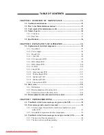
TABLE OF CONTENTS
CHAPTER 1 OVERVIEW OF MAINTENANCE ..................................... 1.1
1-1. Cautions in maintenance ............................................................................. 1.2
1-2. How to use this maintenance manual ......................................................... 1.3
1-3. Tools required for maintenance works ...................................................... 1.3
1-4. Names of parts .............................................................................................. 1.4
1-4-1. Front face ............................................................................................... 1.4
1-4-2. Rear face ................................................................................................ 1.5
1-5. Specifications ................................................................................................ 1.6
CHAPTER 2 EXPLANATION OF OPERATION ..................................... 2.1
2-1. Explanation of electrical components ........................................................ 2.2
2-1-1. Operations ............................................................................................. 2.2
2-1-2. Power supply ......................................................................................... 2.4
2-1-3. Main PCB .............................................................................................. 2.4
2-1-4. 1394 PCB .............................................................................................. 2.8
2-1-5. I/F Connection PCB .............................................................................. 2.8
2-1-6. HDC-4Head PCB .................................................................................. 2.8
2-1-7. HDC-2Head PCB ................................................................................ 2.10
2-1-8. IO PCB ................................................................................................ 2.10
2-1-9. Slider PCB ........................................................................................... 2.11
2-1-10. Linear encoder PCB .......................................................................... 2.13
2-1-11. The KeyBoard PCB ........................................................................... 2.13
2-1-12. Ink Sensor PCB 1 .............................................................................. 2.13
2-1-13. Ink Sensor PCB 2 .............................................................................. 2.13
2-1-14. Take-up motor PCB ........................................................................... 2.13
2-2. Ink system ................................................................................................... 2.14
2-2-1. Definitions ........................................................................................... 2.14
2-2-2. Brief explanation of the ink system ..................................................... 2.15
2-2-3. Parameters related to the ink system ................................................... 2.18
2-3. Brief explanation of media size detection control ................................... 2.19
CHAPTER 3 TROUBLESHOOTING ........................................................... 3.1
3-1. Troubles for which error messages are given on the LCD ...................... 3.2
3-2. Error messages and corrective measures .................................................. 3.3
3-2-1. Error messages for troubles for which error numbers are given
on the LCD ............................................................................................ 3.3
3-2-2. Ink-related components and other components ..................................... 3.6
3-3. Troubles for which error messages are not given on the LCD ................ 3.8
3-3-1. The device will not be energized. .......................................................... 3.8
3-3-2. The device fails to perform plotting ...................................................... 3.9
Downloaded From ManualsPrinter.com Manuals
Содержание JV4-130
Страница 2: ...Downloaded From ManualsPrinter com Manuals ...
Страница 8: ... vi Downloaded From ManualsPrinter com Manuals ...
Страница 9: ... 1 1 CHAPTER 1 OVERVIEW OF MAINTENANCE Downloaded From ManualsPrinter com Manuals ...
Страница 18: ... 1 10 Downloaded From ManualsPrinter com Manuals ...
Страница 19: ... 2 1 CHAPTER 2 EXPLANATION OF OPERATION Downloaded From ManualsPrinter com Manuals ...
Страница 23: ... 2 5 Main PCB block diagram Downloaded From ManualsPrinter com Manuals ...
Страница 38: ... 2 20 Downloaded From ManualsPrinter com Manuals ...
Страница 59: ... 4 1 CHAPTER 4 MAINTENANCE MODE Downloaded From ManualsPrinter com Manuals ...
Страница 130: ... 4 72 Downloaded From ManualsPrinter com Manuals ...
Страница 131: ... 5 1 CHAPTER 5 DISASSEMBLING ASSEMBLING PROCEDURE Downloaded From ManualsPrinter com Manuals ...
Страница 152: ... 5 22 Downloaded From ManualsPrinter com Manuals ...
Страница 153: ... 6 1 CHAPTER 6 ADJUSTMENT Downloaded From ManualsPrinter com Manuals ...
Страница 154: ... 6 2 6 1 Adjusting item list Downloaded From ManualsPrinter com Manuals ...
Страница 168: ... 6 16 Downloaded From ManualsPrinter com Manuals ...
Страница 169: ...Downloaded From ManualsPrinter com Manuals ...
Страница 170: ...D500175 1 00 26102001 MIMAKI ENGINEERING CO LTD 2001 Downloaded From ManualsPrinter com Manuals ...


