


17
PAGE
4939 5258 01
Assembling
the armature
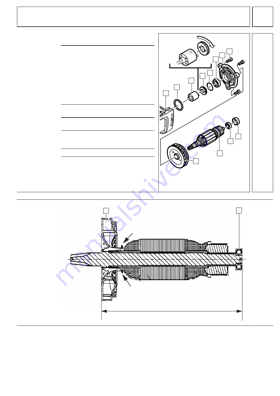
1
Press on the bearing (B) and put on the
rubber sleeve (C).
2
See illustration below:
Press the fan (9) onto the indicated bear-
ing measure. Afterwards, apply some in-
stant glue (e. g. Sicomet) on the armature
shaft (marked with arrows).
☞
The distance between the upper side
of the fan (9) and the lower side of the
bearing (B) must be 159 mm (bearing
measure) according to the below illus-
tration.
3
Press the bearing (6) into the bearing end
plate (7) and insert the locking ring (5).
4
Put the bearing end plate assembly (7) on
the armature.
5
Screw in the seal ring (4) with the
pin-type face spanner (service tool) (3)
(torque = 16 Nm).
6
Insert the seal (2) into the gear box (1).
7
Apply locking agent to the three
screws (8).
Insert the bearing end plate with the
armature (A) into the gear box (1) and
fix them with the three screws (8)
(torque = 4 Nm).
9
2
3
4
5
6
8
7
A
B
C
1
5
Bearing measure: 159 mm
9
B
Instant glue
Instant glue
(e.
g. Sicomet)
(e.
g. Sicomet)


