


7ML19981CX01
ILE-61 Sensing Head – INSTRUCTION MANUAL
Page 15
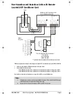
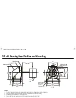
Range Springs
General
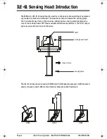
The Range Spring establishes the range of sensing head moving beam travel for a given
range of material flow. This spring installed, is selected and positioned according to the
specified Design Rate of the application.
For best operation the range spring should provide 0.75 to 2.4 mm (0.030 to 0.094") of
moving beam travel from the static zero to the Design rate operation position. The moving
beam travel may be inferred by the value of the LVDT green and yellow (or yellow and
white) wires.
With the 2.5 Vac, 2.9 kHz LVDT excitation supplied:
• 0.75 mm of moving beam movement = 0.188 Vac
• 2.40 mm of moving beam movement = 0.600 Vac
Should the Design Rate of the flowmeter application change, it may be necessary to
reposition the original range spring, or select and install another range spring, to obtain
the optimum moving beam travel (LVDT output) range. Moving the range spring to a
location further away from the pivot point leaf spring, increases the maximum flowrate
capacity.
Range Spring Removal
1.
Observe the range spring mounting position. (3 positions are available)
2.
Loosen the range spring locknut.
3.
Remove the range spring center bolt and 4 flange mounting bolts.
4.
Remove the range spring from the range spring assembly.
Range Spring Replacement
1.
Install the new range spring in the range spring assembly.
2.
Mount the range spring assembly by the 4 flange mounting bolts.
3.
With the moving beam in the static zero position, turn the range spring until the base
just touches the beam, and then turn 1 complete revolution more.
4.
Install the range spring center bolt and tighten the range spring locknut.
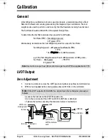
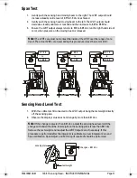
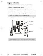
Flowmeter Recalibration
After removing and replacing the range spring, the flowmeter and integrator should be
recalibrated.
1.
Perform the LVDT output Zero procedure. Refer to Calibration.
2.
Perform an integrator Zero and Span calibration. Refer to the integrator manual,
Calibration.
3.
Perform a Span Adjust and Factoring as required. Refer to the integrator manual,
Calibration.
376draft1.fm Page 15 Wednesday, November 21, 2001 1:54 PM
Siemens Industrial
Содержание ILE-61
Страница 1: ...ILE 61 SENSING HEAD November 2001 LE 61 SEINSIING HEA Instruction Manual PL 376...
Страница 24: ......
Страница 25: ...Notes...
Страница 26: ...Notes...
Страница 27: ......
Страница 28: ...7ML19981CX01...


