background image

OM-239 210 Page 3

D

Read and follow instructions on compressed gas cylinders,

associated equipment, and Compressed Gas Association (CGA)

publication P-1 listed in Safety Standards.

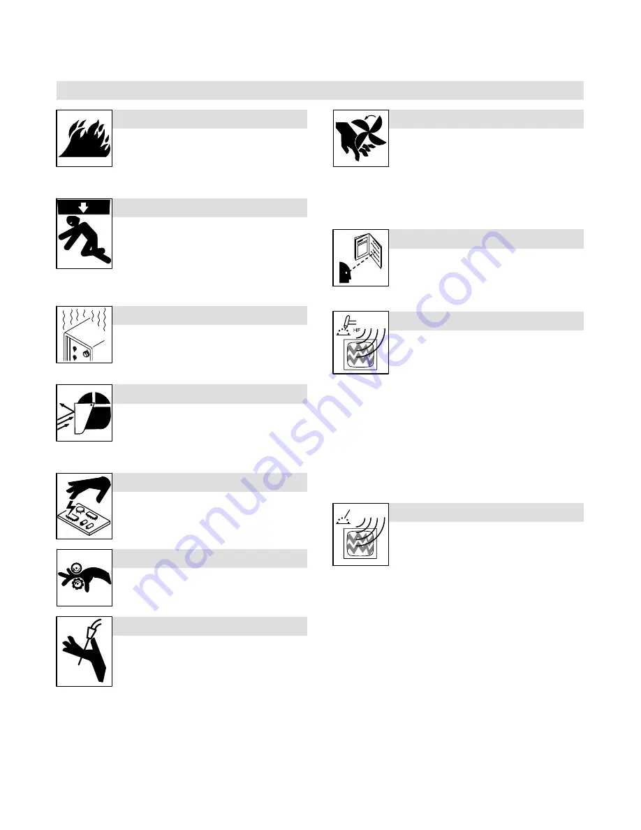
1-3. Additional Symbols For Installation, Operation, And Maintenance

FIRE OR EXPLOSION hazard.

D

Do not install or place unit on, over, or near

combustible surfaces.

D

Do not install unit near flammables.

D

Do not overload building wiring 

 be sure power supply system is

properly sized, rated, and protected to handle this unit.

FALLING UNIT can cause injury.

D

Use lifting eye to lift unit only, NOT running

gear, gas cylinders, or any other accessories.

D

Use equipment of adequate capacity to lift and

support unit.

D

If using lift forks to move unit, be sure forks are

long enough to extend beyond opposite side of

unit.

OVERUSE can cause OVERHEATING

D

Allow cooling period; follow rated duty cycle.

D

Reduce current or reduce duty cycle before

starting to weld again.

D

Do not block or filter airflow to unit.

FLYING SPARKS can cause injury.

D

Wear a face shield to protect eyes and face.

D

Shape tungsten electrode only on grinder with

proper guards in a safe location wearing proper

face, hand, and body protection.

D

Sparks can cause fires — keep flammables away.

STATIC (ESD) can damage PC  boards.

D

Put on grounded wrist strap BEFORE handling

boards or parts.

D

Use proper static-proof bags and boxes to

store, move, or ship PC boards.

MOVING PARTS can cause injury.

D

Keep away from moving parts.

D

Keep away from pinch points such as drive

rolls.

WELDING WIRE can cause injury.

D

Do not press gun trigger until instructed to do

so.

D

Do not point gun toward any part of the body,

other people, or any metal when threading

welding wire.

MOVING PARTS can cause injury.

D

Keep away from moving parts such as fans.

D

Keep all doors, panels, covers, and guards

closed and securely in place.

D

Have only qualified persons remove doors, panels, covers, or

guards for maintenance as necessary.

D

Reinstall doors, panels, covers, or guards when maintenance is

finished and before reconnecting input power.

READ INSTRUCTIONS.

D

Read Owner’s Manual before using or servic-

ing unit.

D

Use only genuine replacement parts from the

manufacturer.

H.F. RADIATION can cause interference.

D

High-frequency (H.F.) can interfere with radio

navigation, safety services, computers, and

communications equipment.

D

Have only qualified persons familiar with

electronic equipment perform this installation.

D

The user is responsible for having a qualified electrician prompt-

ly correct any interference problem resulting from the installa-

tion.

D

If notified by the FCC about interference, stop using the

equipment at once.

D

Have the installation regularly checked and maintained.

D

Keep high-frequency source doors and panels tightly shut, keep

spark gaps at correct setting, and use grounding and shielding to

minimize the possibility of interference.

ARC WELDING can cause interference.

D

Electromagnetic energy can interfere with

sensitive electronic equipment such as

computers and computer-driven equipment

such as robots.

D

Be sure all equipment in the welding area is

electromagnetically compatible.

D

To reduce possible interference, keep weld cables as short as

possible, close together, and down low, such as on the floor.

D

Locate welding operation  100 meters from any sensitive elec-

tronic equipment.

D

Be sure this welding machine is installed and grounded

according to this manual.

D

If interference still occurs, the user must take extra measures

such as moving the welding machine, using shielded cables,

using line filters, or shielding the work area.

Содержание XR-ALUMAFEED

Страница 1: ...XR AlumaFeed Processes Description OM 239 210A 2009 01 MIG GMAW Welding Wire Feeder And Feeder Gun File MIG GMAW Visit our website at www MillerWelds com...

Страница 2: ...tinue the tradition They re just as committed to providing equipment and service that meets the high standards of quality and value established in 1929 This Owner s Manual is designed to help you get...

Страница 3: ...ns 13 SECTION 5 INSTALLATION 13 5 1 Connections With A Constant Voltage CV Or Constant Current Constant Voltage CC CV Welding Power Source Having A 14 Socket Receptacle 13 5 2 Air Cooled Feeder Connec...

Страница 4: ......

Страница 5: ...cramped positions such as sitting kneeling or lying or when there is a high risk of unavoid able or accidental contact with the workpiece or ground For these conditions use the following equipment in...

Страница 6: ...dden side D Do not weld on closed containers such as tanks drums or pipes unless they are properly prepared according to AWS F4 1 see Safety Standards D Do not weld where the atmosphere may contain fl...

Страница 7: ...ding wire MOVING PARTS can cause injury D Keep away from moving parts such as fans D Keep all doors panels covers and guards closed and securely in place D Have only qualified persons remove doors pan...

Страница 8: ...York NY 10036 8002 phone 212 642 4900 website www ansi org Standard for Fire Prevention During Welding Cutting and Other Hot Work NFPA Standard 51B from National Fire Protection Association P O Box 91...

Страница 9: ...source lectrique courant lectrique s av re n cessaire se servir de la fonction de t l commande si l appareil en est quip D D autres consignes de s curit sont n cessaires dans les condi tions suivantes...

Страница 10: ...de protection Le soudage effectu sur des conteneurs ferm s tel que des r servoirs tambours ou des conduites peu provoquer leur clatement Des tincelles peuven tre projet es de l arc de soudure La proje...

Страница 11: ...e pour usage ult rieur D Utiliser les quipements corrects les bonnes proc dures et suffi samment de personnes pour soulever et d placer les bouteilles D Lire et suivre les instructions sur les bouteil...

Страница 12: ...de provoquer des interf rences D L nergie lectromagn tique risque de provo quer des interf rences pour l quipement lec tronique sensible tel que les ordinateurs et l quipement command par ordinateur t...

Страница 13: ...O Box 371954 Pittsburgh PA 15250 7954 t l phone 1 866 512 1800 il y a 10 bureaux r gionaux le t l pho ne de la r gion 5 Chicago est 312 353 2220 site Internet www osha gov 2 6 Information EMF Consid r...

Страница 14: ...OM 239 210 Page 10...

Страница 15: ...g fumes can be hazardous to your health 2 1 Keep your head out of the fumes 2 2 Use forced ventilation or local exhaust to remove the fumes 2 3 Use ventilating fan to remove fumes 3 Welding sparks can...

Страница 16: ...Definitions Some symbols are found only on CE products A Amperes V Volts Alternating Current X Duty Cycle IP Degree Of Protection Hz Hertz Circuit Breaker Wire Feed Jog Output Trigger Gun Press To Se...

Страница 17: ...1 6 mm Max Spool Capacity 12 in 305 mm 400 A 100 Duty Cycle Length 21 1 4 in 540 mm Width 9 1 2 in 241 mm Height 16 in 406 mm 42 5 lb 19 2 kg System Duty Cycle is Limited to Gun Rating SECTION 5 INSTA...

Страница 18: ...epare weld cable according to welding power source manual 3 Weld Cable Grommet 4 Current Sensing Reed Relay 5 Weld Cable Terminal In Feeder Route one end of weld cable through grommet through reed rel...

Страница 19: ...Control Cable Insert plug into Gun Control receptacle and tighten threaded collar 2 Gun Power Pin 3 Gun Bushing 4 Gun Securing Knob 5 Drive Casting Loosen gun securing knob and insert gun power pin th...

Страница 20: ...lding power source 6 Coolant Hose Grommet 7 Location Of Coolant Fittings On Front Panel Route one end of a coolant hose through grommet and connect to rear of Coolant Out fitting in feeder Connect rem...

Страница 21: ...4 Gun Bushing 5 Drive Casting Loosen gun securing knob and insert gun power pin through gun bushing until it bottoms against drive casting Tighten knob Close and latch door 6 Gun Coolant In Hose Conn...

Страница 22: ...0 to 10 volts DC 1 volt per 10 arc volts F Current feedback 0 to 10 volts DC 1 volt per 100 amperes L 0 to 10 volts DC output signal from wire feeder to power source with respect to socket N N Feeder...

Страница 23: ...150 mm 1 Tension Arm Open tension arm Thread wire thru inlet guide along drive roll groove and into wire conduit Close tension arm Adjust tension as follows Hold wire tightly to keep it from unravelin...

Страница 24: ...Menu Indicator 9 Start Menu Indicator 10 Left Display 11 Lock Indicator 12 Setup Menu Indicator 13 Right Display 14 Schedule B Indicator 15 Advanced Trigger Indicator 16 Wire Speed Indicator 17 Amps I...

Страница 25: ...ter are automatically active and cannot be turned off in 4T mode In 4T mode press and hold the gun trigger to begin welding at the Start parameter settings Release the gun trigger and welding will con...

Страница 26: ...Pulsed MIG welding the selected DISP parameter ARC L or VOLT is lit under the Left Dis play and the WIRE SPEED INDICATOR is lit under the Right Display The arc length or voltage is adjusted using the...

Страница 27: ...rigger hold time is always 4 0 seconds after the trigger hold delay time For Example if the trigger hold delay time is set to 2 0 seconds the trigger must be held for at least 2 0 seconds and re lease...

Страница 28: ...he gun to the feeder and thread the wire thru the con tact tip Set the drive roll tension setting to 3 4 see Section 5 8 Press and hold the gun trigger The feeder will begin feeding wire with the powe...

Страница 29: ...ed used during the Start Time This setting is a percentage of the wirefeed speed the unit is set to for welding Range of this setting is from X0 5 to X2 50 Example If the weld wirefeed speed is 200 an...

Страница 30: ...the wirefeed speed the unit is set to for welding Range of this setting is from X0 30 to X1 00 Example If the weld wirefeed speed is 200 and WFS is X0 50 the Crater Wirefeed Speed is 100 Crater Arc L...

Страница 31: ...or off Profile Pulse Frequency P FRQ Sets the spacing between ripples in the weld bead Range of this setting is from 0 1 to 5 0 pulses per second See Figures 1 and 2 below Profile Pulse Wirefeed Speed...

Страница 32: ...ol 1 Pressure Roll Assembly 2 Drive Motor Shaft 3 Drive Roll 4 Screw Use wire brush to clean drive roll 5 Drive Roll Idler 6 Shoulder Washers Use wire brush to clean idler 7 Outlet Guide 8 Wire Inlet...

Страница 33: ...the purge switch is held when the feeder is powered up The error may be cleared by releasing the purge switch COOL ERR Indicates a water flow switch error A water flow switch error occurs if no water...

Страница 34: ...e contact tip Verify proper wire size is selected see Section 7 2 Check drive roll pressure in wire feeder and gun see Section 5 8 Check and replace liner if necessary Wire does not feed burnback in c...

Страница 35: ...OM 239 210 Page 31 Notes...

Страница 36: ...OM 239 210 Page 32 SECTION 9 ELECTRICAL DIAGRAMS Figure 9 1 Circuit Diagram For Wire Feeder...

Страница 37: ...OM 239 210 Page 33 239 209 B...

Страница 38: ...not available unless listed 242 437 A 54 Figure 10 2 53 Figure 10 3 1 2 3 4 5 6 7 9 10 11 12 13 14 15 17 18 19 21 22 23 24 27 29 30 31 32 28 33 39 41 38 40 43 42 45 44 51 55 56 59 60 61 28 16 34 35 36...

Страница 39: ...8Hex 41H Nyl 1 28 073 302 Bearing Ball Rdl Sgl Row 669 X 1 378 X 39 2 29 113 161 Block Bearing Front 2 30 113 165 Stand Off 250 20 X 1 000 Lg 4 31 120 396 Shaft Spool 1 32 MP1 163 304 Brake W Terminal...

Страница 40: ...displaying a precautionary label the label should also be ordered Part of 194 146 KIT Water Connection Recommended Spare Parts To maintain the factory original performance of your equipment use only...

Страница 41: ...17 058 549 Guide Wire Inlet 1 16 1 18 602 306 Pin Spring Cs 125 X 500 2 19 189 823 Insulator Front Bearing 1 20 189 920 Gear Assy Shaft Bearing 1 21 189 605 Bearing Assy Upper Drive Shaft 1 22 192 929...

Страница 42: ...0 28 69Hex 28H Brs Conical Knurl 2 3 Nameplate Order By Model And Serial Number 1 4 239 217 Panel Front 1 5 231 470 Nut Adapter Encoder Shaft Mtg 375 32 To 500 28 2 6 190 512 Stand off No 6 32 X 640 L...

Страница 43: ...s MIG Guns and Subarc SAW Guns Induction Heating Coils and Blankets Cables and Non Electronic Controls APT SAF Model Plasma Cutting Torches Remote Controls Accessory Kits Replacement Parts No labor Sp...

Страница 44: ...your personal records Always provide Model Name and Serial Style Number Contact a DISTRIBUTOR or SERVICE AGENCY near you Welding Supplies and Consumables Options and Accessories Personal Safety Equip...

Отзывы: