


OM-253555 Page 16
�
Complete Parts List is available at www.MillerWelds.com
SECTION 5 – INSTALLATION
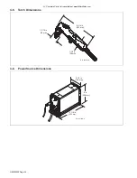
5-1.
Selecting A Location
Movement
1
Location And Airflow
loc_small 2018-08
2
18 in.
(460 mm)
18 in.
(460 mm)
Do not move or operate unit where
it could tip.
Special installation may be re-
quired where gasoline or volatile
liquids are present — see NEC Ar-
ticle 511 or CEC Section 20.
1
Shoulder Strap
Use strap to lift unit.
2
Line Disconnect Device
Locate unit near correct input power supply.
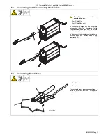
5-2.
Connecting Gas/Air Supply
OM-253555 Page 1
Ref. 251808-A
3
1
2
OM-222 Page 1
allen_wrench
NGO’s
tools/
flathead
philips head
wrench
pliers
knife
heavy-duty workclamp
light-duty workclamp
wirecutter
frontcutter
allen_set
needlenose
steelbrush
nutdriver
chippinghammer
solderiron
stripcrimp
drill
torque wrench
socket wrench
hammer
awl
file
crimper
paintbrush
feelergauge
flashlight
ruler
toothbrush
greasegun
qtip (swab)
vicegrip
handream
punch
filterwrench
strapwrench
airgun
solvent
pinextractor
eprompuller
pipewrench
torque screwdriver
crescent wrench
9/16 in.
�
Use only clean, dry air with 90 to 120
psi (621 to 827 kPa) pressure.
1
Gas/Air Inlet Opening
2
Hose (From Gas/Air Supply)
3
Teflon Tape
Obtain hose with 1/4 NPT right-hand thread
fitting. Wrap threads with Teflon tape (option-
al) or apply pipe sealant, and install fitting in
opening. Route hose to gas/air supply.
Содержание Spectrum 375 X-TREME
Страница 4: ......
Страница 37: ...OM 253555 Page 33 ...
Страница 38: ...OM 253555 Page 34 SECTION 8 ELECTRICAL DIAGRAMS Figure 8 1 Circuit Diagram ...
Страница 39: ...OM 253555 Page 35 286338 A ...
Страница 42: ...Notes ...


