


TABLE OF CONTENTS
. . . . . . . . . . . . . . . . . . . . . . . . . . . . . . . .
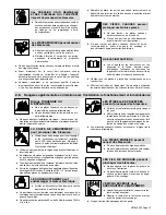
1-6. Additional Symbols For Installation, Operation, And Maintenance
. . . . . . . . . . . . . . . . . . . . . . . . . . . .
1-7. California Proposition 65 Warnings
1-8. Principal Safety Standards
. . . . . . . . . . . . . . . . . . . . . . . . . .
2-1. Signification des symboles
2-2. Dangers relatifs au soudage à l’arc
2-3. Dangers existant en relation avec le moteur
. . . . . . . . . . . . . . . . . . . . . . . . . . . . . . . . . . . . . . . . . . . . . .
2-4. Dangers liés à l’hydraulique
2-5. Dangers liés à l’air comprimé
2-6. Dangers supplémentaires en relation avec l’installation, le fonctionnement et la maintenance
2-7. Proposition californienne 65 Avertissements
. . . . . . . . . . . . . . . . . . . . . . . . . . . . . . . . . . . . . . . . . . . . . .
2-8. Principales normes de sécurité
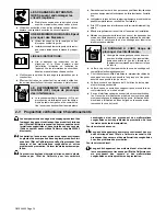
2-9. Informations relatives aux CEM
4-1. Weld, Power, And Engine Specifications
. . . . . . . . . . . . . . . . . . . . . . . . . . . . . . . . . . . . . . . . . . . . . . . . .
4-3. Dimensions, Weights, And Operating Angles
. . . . . . . . . . . . . . . . . . . . . . . . . . . . . . . . . . . . . . . . . . . . .
4-4. Stick And MIG Volt-Ampere Curves
4-5. DC TIG Volt-Ampere Curves
5-1. Serial Number And Rating Label Location
. . . . . . . . . . . . . . . . . . . . . . . . . . . . . . . . . . . . . . . . . . . . . . . .
5-2. Installing Welding Generator
5-3. Mounting Welding Generator
5-4. Grounding Generator To Truck Or Trailer Frame
. . . . . . . . . . . . . . . . . . . . . . . . . . . . . . . . . . . . . . . . . .
5-6. Installing Optional Spark Arrestor Muffler
. . . . . . . . . . . . . . . . . . . . . . . . . . . . . . . . . . . . . . . . . . . . . . . . .
5-7. Activating The Dry Charge Battery (If Applicable)
. . . . . . . . . . . . . . . . . . . . . . . . . . . . . . . . . . . . . . . . . .
5-9. Using The Optional Battery Disconnect Switch
. . . . . . . . . . . . . . . . . . . . . . . . . . . . . . . . . . . . . . . . . . . .
5-11. Connecting To Weld Output Terminals
5-12. Selecting Weld Cable Sizes*
5-13. Connecting To Remote 14 Receptacle RC14
. . . . . . . . . . . . . . . . . . . . . . . . . . . . . . . . . . . . . . . . . . . . .
5-14. Connections To Terminal Strip T10
OPERATING THE WELDING GENERATOR
. . . . . . . . . . . . . . . . . . . . . . . . . . . . . . . . . . . . . . .
6-1. Controls (See Section 6-2)
6-2. Description Of Controls (See Section 6-1)
. . . . . . . . . . . . . . . . . . . . . . . . . . . . . . . . . . . . . . . . . . . . . . . .
6-4. Using Remote Voltage/Amperage Control
. . . . . . . . . . . . . . . . . . . . . . . . . . . . . . . . . . . . . . . . . . . . . . . .
6-5. Fuel/Hour Gauge Descriptions
. . . . . . . . . . . . . . . . . . . . . . . . . . . . . . . . . . . . . . . . . . .
Содержание Big Blue 800
Страница 40: ...OM 244 023 Page 36 6 5 Fuel Hour Gauge Descriptions ...
Страница 43: ...OM 244 023 Page 39 8 2 Engine Maintenance Label ...
Страница 52: ...OM 244 023 Page 48 SECTION 10 ELECTRICAL DIAGRAM Figure 10 1 Circuit Diagram For Welding Generator ...
Страница 53: ...OM 244 023 Page 49 244 022 B ...
Страница 76: ...OM 244 023 Page 72 Notes Ref AWS ANSI A2 4 Welding Symbols ...


