
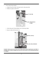
3
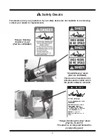
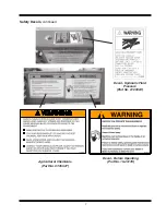
Safety Precautions
This symbol is used to call your attention to instructions concerning your
personal safety. Be sure to observe and follow these instructions. Take time
to be careful!
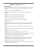
DANGER
“DANGER” indicates an imminently hazardous situation which, if not avoided,
will result in death or serious injury.
WARNING
“WARNING” indicates a potentially hazardous situation which, if not avoided,
could result in death or serious injury.
CAUTION
“CAUTION” indicates a potentially hazardous situation which, if not
avoided, may result in minor or moderate injury. It may also alert against
unsafe practices.
BEFORE you attempt to operate this machine, read and study the following safety informa-
tion. In addition, MAKE SURE that every individual who operates or works with this equip-
ment, whether family member or employee, is familiar with these safety precautions. Miller-
St. Nazianz provides guards for exposed moving parts for the operator’s protection; how-
ever, some areas cannot be guarded or shielded in order to assure proper operation. The
OPERATOR’S MANUAL AND DECALS on the machine itself warn you of dangers and
SHOULD BE READ AND OBSERVED CLOSELY.
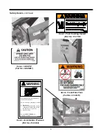
Power Source Shutdown Procedure
Before cleaning, unclogging, adjusting, lubricating or servicing this machine:
1. Disengage the tractor PTO.
2. Deactivate tractor hydraulic controls.
3. Shut off the tractor engine, remove the starter key and take it with you.
4. Wait for all machine motion to stop.
5. Remove the telescoping PTO driveline and ALL power connections from
the tractor.
Failure to follow these precautions could result in death or serious injury.
Содержание 500 BW
Страница 6: ......
Страница 31: ...27 Spray Tip Wear...
Страница 38: ...34 TeeJet Air Induction Spray Tips At Various Speeds And Pressures 20 Inch Tip Spacing...
Страница 45: ...41 TeeJet FloodJet Wide Angle Flat Spray Tips At Various Speeds And Pressures 40 Inch Tip Spacing...
Страница 58: ...54 Instructions Valve Settings For Accessory Kits Refer To The Operator s Manual For Detailed Instructions...
Страница 94: ......
Страница 96: ...2007 by Miller St Nazianz Inc...