background image

OPERATING INSTRUCTIONS

6

The Operating Instructions for Arrow series fluid heads are
described in six (6) steps. Please read and understand these
instructions before using this equipment. Do not omit any
step.

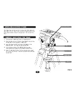
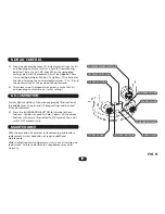
1.1 Unscrew the CLAMP NUT from its threaded stud.

1.2 Place the head in your 100mm tripod bowl and re-fit the

CLAMP NUT. Do not tighten CLAMP NUT.

1.3 Level the fluid head by centering the bubble in the

BUBBLE LEVEL. Then tighten the CLAMP NUT.

1.4 In low light conditions the BUBBLE LEVEL can be

illuminated by pressing the ILLUMINATION BUTTON.

1.5 Note: If adjusting the level with your camera mounted, 

first ensure the camera is securely held before loosening 
CLAMP NUT.

1 INSTALL AND LEVEL THE HEAD

ILLUMINATION BUTTON

BUBBLE LEVEL

TRIPOD BOWL

THREADED STUD

CLAMP NUT

FIG 3

Содержание 1012

Страница 1: ...The Arrow Series Fluid Head Operator s Manual 1020 Arrow 30 with Euro camera platform 1012 Arrow with Euro camera platform 1014 Arrow HD with Euro camera platform ...

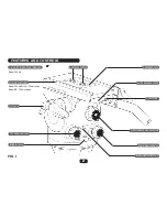
Страница 2: ...row HD 100mm range Arrow 30 only CAMERA SCREWS 1 4 AND PIN ADAPTOR CARRIAGE CAMERA PLATE QUICK RELEASE LEVER SAFETY TAB COUNTERBALANCE SELECTOR PAN DRAG CONTROL ILLUMINATION BUTTON TILT LOCK TILT DRAG CONTROL BUBBLE LEVEL FEATURES AND CONTROLS 2 FIG 1 ...

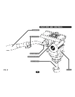
Страница 3: ...FEATURES AND CONTROLS 3 FIG 2 PAN HANDLE TELESCOPIC CLAMP PAN HANDLE CLAMP SLIDING PLATFORM LOCK BOWL CLAMP NUT PAN LOCK ...

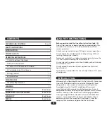
Страница 4: ...handle To prevent accidental or sudden movement do not release the TILT LOCK without holding the PAN HANDLE Do not release the clamp nut without holding either the head or attached camera Do not exceed the maximum total payload see Technical Specifications The operator is responsible for the safe operation of this piece of equipment Welcome to the Operating Manual for the Arrow 30 Arrow and Arrow ...

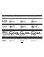
Страница 5: ...tem Calliper disc brake system Calliper disc brake system COUNTERBALANCE 4 selectable positions 4 selectable positions 4 selectable positions CAMERA PLATFORM Euro quick release camera plate in Euro quick release camera plate in Euro quick release camera plate in sliding camera balance platform sliding camera balance platform sliding camera balance platform Camera Attachment 3 8 1 4 screws 1 4 pin ...

Страница 6: ... tripod bowl and re fit the CLAMP NUT Do not tighten CLAMP NUT 1 3 Level the fluid head by centering the bubble in the BUBBLE LEVEL Then tighten the CLAMP NUT 1 4 In low light conditions the BUBBLE LEVEL can be illuminated by pressing the ILLUMINATION BUTTON 1 5 Note If adjusting the level with your camera mounted first ensure the camera is securely held before loosening CLAMP NUT 1 INSTALL AND LE...

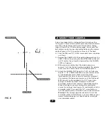
Страница 7: ...nce the camera on a rod or similar to find balance point 2 4 Attach the CAMERA PLATE over the C of G by fastening the 3 8 1 4 CAMERA SCREWS into your camera s base or tripod adaptor plate These screws should be tightened evenly and as far apart as possible to prevent any movement between your camera and the fluid head N B Arrow 30 is also supplied with a 1 4 screw pin carriage Cat 493 for direct a...

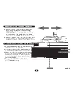
Страница 8: ... camera should be firmly attached with no obvious free movement SLIDING PLATFORM SLIDING PLATFORM LOCK CENTRE AXIS FIG 5 3 CENTRE YOUR CAMERA ON THE HEAD 3 1 With your camera attached to the fluid head hold the PAN HANDLE and release the TILT LOCK 3 2 Turn the TILT DRAG CONTROL knob to position 0 Turn the COUNTERBALANCE SELECTOR knob to position 1 3 3 Release the SLIDE LOCK lever and slide your ca...

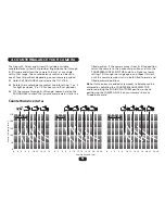
Страница 9: ...ur camera remains static in a tilted position If the camera moves from its tilted position return the camera to the horizontal position and turn the COUNTERBALANCE SELECTOR knob to a higher or lower setting Tilt through the range again and repeat this test until the camera remains static in both tilted forward and tilted backward positions Note If accessories are added or removed re balance can be...

Страница 10: ...sure that tilt and pan drag controls are on similar settings For low light conditions Arrow heads provide illumination of the bubble level the pan and tilt drag settings and pan and tilt knob indicators 6 1 Press the ILLUMINATION BUTTON to illuminate these features You do not need to hold it down All the above features will remain illuminated for 10 seconds then will switch OFF automatically With ...

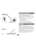
Страница 11: ...R and RETAINING SCREWS 7 5 Press the ILLUMINATION BUTTON to test operation WARNING Do not immerse in any liquid WARNING Do not use stiff brushes abrasives or solvents Arrow heads feature protective coatings dust and moisture seals and anti corrosive fittings to ensure long and trouble free operation even in harsh environments To ensure optimum performance through the life of the head Miller recomm...

Страница 12: ...irement may void warranty It is advisable to notify Miller or a Miller Authorised Service Agent if a change of performance is observed as a result of dropping or rough usage For information regarding sales and service of Miller products or for your nearest Miller representative please contact us via our website or at the following MILLER CAMERA SUPPORT EQUIPMENT 30 Hotham Parade Artarmon Sydney NS...

Отзывы: