


OM-4433 Page 40
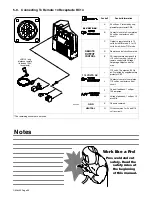
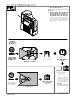
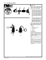
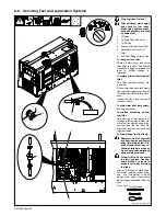
8-8. Servicing Fuel And Lubrication Systems
802 490 / Ref. 801 434
!
Stop engine and let cool.
!
After servicing, start engine
and check for fuel leaks.
Stop engine, tighten connec-
tions as necessary, and wipe
up spilled fuel.
1
Oil Filter
2
Oil Drain Valve And Hose
3
Oil Fill Cap
4
Primary (Canister) Fuel Filter
5
Secondary (In-Line) Fuel
Filter
6
Fuel Tank Sludge Drain Valve
To change oil and filter:
Route oil drain hose and valve
through hole in base. See engine
manual and engine maintenance
label for oil/filter change in-
formation.
To replace primary (canister) fuel
filter:
Turn filter counterclockwise. Re-
move filter.
Fill new filter with fresh fuel. Apply
thin coat of fuel to gasket on new fil-
ter. Install new filter and turn clock-
wise.
Inspect fuel lines, and replace if
cracked or worn.
To drain water from fuel system:
See engine manual.
To replace secondary (in-line)
fuel filter:
Note direction of fuel flow as indi-
cated by arrow on side of filter. Re-
move fuel line clamps and discon-
nect fuel lines from fuel filter. Re-
place filter, reconnect fuel lines, and
reinstall clamps.
To drain sludge from fuel tank:
!
Beware of fire. Do not smoke
and keep sparks and flames
away from drained fuel. Dis-
pose of drained fuel in an en-
vironmentally-safe manner.
Do not leave unit unattended
while draining fuel tank.
!
Properly lift unit and secure
in a level position. Use ade-
quate blocks or stands to
support unit while draining
fuel tank.
Attach 1/2 ID hose to drain valve.
Put metal container under drain,
and use screwdriver to open
sludge drain valve. Close valve
when sludge has drained. Remove
hose.
Close door. Tools Needed:
6
3
5
2
4
1
Содержание Big Blue 300 P
Страница 17: ...OM 4433 Page 13 3 2 Manufacturer s Rating Label 228 417 B 803 562 F ...
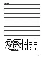
Страница 31: ...OM 4433 Page 27 Notes Welding Symbols Ref AWS ANSI A2 4 ...
Страница 39: ...OM 4433 Page 35 8 2 Maintenance Label ...
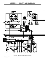
Страница 52: ...OM 4433 Page 48 SECTION 9 ELECTRICAL DIAGRAMS Figure 9 1 Circuit Diagram For Welding Generator ...
Страница 53: ...OM 4433 Page 49 219 228 E ...