background image

Quick Start Guide

www.milesight.com

30

5.8 Mini PTZ Bullet Network Camera

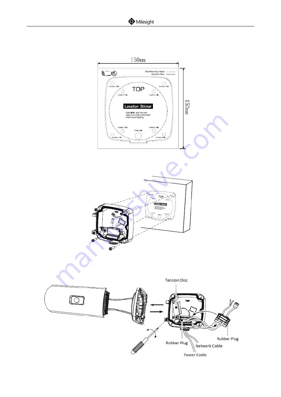
Step1: Fix a sticker in the position where you want to install your camera;

Step2: Pass the Ethernet cable through the rear cover and fasten the rear cover to the ceiling or

wall;

Step3: Remove tension disc and get your cables through the rubber plug, fix the tension disc again

then connect the cables correctly;

Содержание Network camera

Страница 1: ......

Страница 2: ......

Страница 3: ... 12 4 10 Speed Dome Network Camera 13 5 Hardware Installation 14 5 1 Mini Dome Network Camera 14 5 2 IR Mini Dome Network Camera 15 5 3 Vandal proof Mini Dome Network Camera 18 5 4 Wi Fi Mini Cube Network Camera 20 5 5 Mini Bullet Network Camera 22 5 6 Pro Bullet Network Camera 24 5 7 Pro Dome Network Camera 26 5 8 Mini PTZ Bullet Network Camera 30 5 9 Speed Dome Network Camera 32 6 How to Connect...

Страница 4: ......

Страница 5: ... Power Adapter 1 PC DC 12V optional for part of devices Quick Start Guide 1 PC Printed material Warranty Card 1 PC Printed material Optional Lens If purchased Bracket Screw Pack If purchased 2 Cautions Do not expose the product to rain or moisture Make sure the device is firmly fixed when mounting them on the wall or ceiling Make sure that the power supply voltage is correct before using the camer...

Страница 6: ...work Camera Figure 4 1 Mini Dome Network Camera Note 1 Error LED Indicator Error LED Indicator is on when the device starts up or runs error 2 Reset Button Press Reset button for 5 seconds the device will be restored to factory default 3 Only PoE is available for power supply ...

Страница 7: ...lesight com 3 4 2 IR Mini Dome Network Camera Figure 4 2 IR Mini Dome Network Camera Note 1 Reset Button Press Reset button for 5 seconds the device will be restored to factory default 2 Only PoE is available for power supply ...

Страница 8: ...a Figure 4 3 Vandal proof Mini Dome Network Camera Note 1 Error LED Indicator Error LED Indicator is on when the device starts up or runs error 2 Reset Button Press Reset button for 5 seconds the device will be restored to factory default 3 Only PoE is available for power supply ...

Страница 9: ...on Press this button and then press the WPS button on your router to set up wireless connection automatically 3 DC 12V and PoE are available for power supply 4 Reset Button Press Reset button for 5 seconds the device will be restored to factory default Microphone Lens Light Sensor IR LEDs LED Indicators Speaker PIR Sensor or SIP Button Micro SD SDHC SDXC Card Slot SIP Button Ethernet Port PoE WPS ...

Страница 10: ...ilesight com 6 4 5 Mini Bullet Network Camera Figure 4 5 Mini Bullet Network Camera Note 1 Only PoE is available for power supply 2 Reset Button Press Reset button for 5 seconds the device will be restored to factory default ...

Страница 11: ...mote Focus Zoom Mini Bullet Network Camera Figure 4 6 Remote Focus Zoom Mini Bullet Network Camera Note 1 DC 12V and PoE are available for power supply 2 Reset Button Press Reset button for 5 seconds the device will be restored to factory default ...

Страница 12: ...a Figure 4 7 Pro Bullet Network Camera Note 1 There are two versions for Pro Bullet the interface s pictures are as following 2 DC 12V and PoE are available for power supply 3 Reset Button Press Reset button for 5 seconds the device will be restored to factory default ...

Страница 13: ...Quick Start Guide www milesight com 9 Figure 4 8 Pro Bullet Network Camera Version A Figure 4 8 Pro Bullet Network Camera Version B ...

Страница 14: ...Quick Start Guide www milesight com 10 4 8 Pro Dome Network Camera Note 1 Reset Button Press Reset button for 5 seconds the device will be restored to factory default ...

Страница 15: ...k Start Guide www milesight com 11 Figure 4 9 Pro Dome Network Camera multiple interface Here is one equipped cable for multiple interface usage Figure 4 10 Pro Dome Network Camera multiple interface cable ...

Страница 16: ...Quick Start Guide www milesight com 12 4 9 Mini PTZ Bullet Network Camera Figure 4 11 Mini PTZ Bullet Network Camera Note 1 Only DC 12V is available for power supply ...

Страница 17: ...esight com 13 4 10 Speed Dome Network Camera Figure 4 12 Speed Dome Network Camera Note 1 DC 12V and AC 24V are available for power supply 2 Built in SD card slot can be seen after removing the 4 screws and open the front panel ...

Страница 18: ...Start Guide www milesight com 14 5 Hardware Installation 5 1 Mini Dome Network Camera Step1 Remove the dome cover Step2 Secure the screws Step3 Connect and route an Ethernet cable through the ceiling or wall ...

Страница 19: ...Quick Start Guide www milesight com 15 Step4 Adjust the lens angle and focus Step5 Attach the dome cover 5 2 IR Mini Dome Network Camera Step1 Remove the dome cover ...

Страница 20: ...Quick Start Guide www milesight com 16 Step2 Secure the screws to wall or bracket please notice to get the cable through the bracket firstly Step3 Connect and route an Ethernet cable ...

Страница 21: ...Quick Start Guide www milesight com 17 Step4 Attach the dome cover Step5 Adjust the lens angle and focus ...

Страница 22: ...Quick Start Guide www milesight com 18 5 3 Vandal proof Mini Dome Network Camera Step1 Remove the dome cover Step2 Secure the screws to the wall or bracket ...

Страница 23: ...Quick Start Guide www milesight com 19 Step3 Connect and route an Ethernet cable Step4 Loosen the screw and adjust the lens angle and focus then screw it tight again ...

Страница 24: ...Quick Start Guide www milesight com 20 Step5 Attach the dome cover 5 4 Wi Fi Mini Cube Network Camera Step1 Mount the cube camera to the ceiling or wall or place the cube camera horizontally ...

Страница 25: ...Quick Start Guide www milesight com 21 Step2 Connect the power adapter and Ethernet cable Step3 Adjust the shooting direction ...

Страница 26: ... rear cover Step3 Install a Micro SD SDHC SDXC card connect an Ethernet cable and pass it through the rubber seal Step4 Install and tighten the rear cover Step5 Tighten the rubber seal seal clamp and cap nut of the waterproof connector Step6 Pass the Ethernet cable through the center of the mount bracket put the bracket and camera together rotate the bracket and fasten the bracket using screws ...

Страница 27: ...Quick Start Guide www milesight com 23 Step7 Mount the camera to the ceiling or wall Step8 Adjust the shooting direction ...

Страница 28: ...rk Camera could only be moved forward for 5mm at most to ensure better field of view 2 It will be much easier to remove the rubber seal with a screwdriver when tearing down the camera 5 6 Pro Bullet Network Camera Step1 Fix a sticker in the position where you want to install your camera ...

Страница 29: ... 25 Step2 Pass the Ethernet cable through the rear cover and fasten the rear cover to the ceiling or wall Step3 Remove tension disc and get your cables through the rubber plug fix the tension disc again then connect the cables correctly ...

Страница 30: ... rear cover and fasten the bracket to the camera using 4 plum flower head screws Step5 Adjust the shooting direction 5 7 Pro Dome Network Camera Step1 Fix a sticker in the position where you want to install your camera Install the supplied bracket on the ceiling or wall secure the screws ...

Страница 31: ...lesight com 27 Step2 Connect an Ethernet and pass it through the rubber seal Step3 Rotate the camera unit according to the direction shown in the picture and then attach the camera unit to the bracket with the supplied screws ...

Страница 32: ...n Ethernet cable and the power source through the ceiling or wall then attach the camera unit to the bracket Step5 Loosen the camera head fixing screw Adjust the camera to turn the lens in the desired direction Tighten the camera head fixing screw to fix the camera ...

Страница 33: ...Quick Start Guide www milesight com 29 Step6 Attach the dome cover and please place the raised position to align to the hole as the following pictures then screw it tight ...

Страница 34: ...cker in the position where you want to install your camera Step2 Pass the Ethernet cable through the rear cover and fasten the rear cover to the ceiling or wall Step3 Remove tension disc and get your cables through the rubber plug fix the tension disc again then connect the cables correctly ...

Страница 35: ...the camera using 4 plum flower head screws Step5 Screw the screws to the installed wall Step6 If you need to use the SD card with the camera please remove the screw of the top cover and pull out the cover then loosen the screws to get access to the SD card slot After inserting SD card screw the screws again ...

Страница 36: ...ould be able to bear the weight eight times larger than the camera s Step2 Use the wall hanging holder to mark the holes Drill 4 holes on the wall Step3 Put the cables through the holder match the holder with the camera body screw holes and secure them Step4 The camera body has been installed to the holder match the holder to the holes on the wall and secure the screws ...

Страница 37: ...Output NC NO 24V DC 1A PIN3 Alarm Input NC NO 12V PIN4 Alarm Input NC NO 12V 7 How to Connect the Water proof Connector Step1 Get the network cable through the screw nut rubber ring and the screw bolt Step2 Insert the rubber ring into the screw bolt Step3 Connect the screw nut to the screw bolt Step4 Place the O Ring on the network port connector Step5 Connect to RJ45 and the connector of camera s...

Страница 38: ...amera in the same LAN of your computer 8 1 1 Assigning an IP Address by Using Smart Tools Smart Tools is a software tool which can automatically detect multiple online Milesight network cameras connected in the LAN set IP addresses and manage firmware upgrades It s recommended when assigning IP addresses for multiple cameras Step1 Install Smart Tools The software could be downloaded from our websi...

Страница 39: ...Quick Start Guide www milesight com 35 Step3 Select a camera or multiple cameras according to the MAC addresses Figure 8 2 Select single camera Figure 8 3 Select multiple cameras ...

Страница 40: ...Start Guide www milesight com 36 Step4 Type the User Name and Password if they are not the default value Figure 8 4 Step5 Change the IP address or other network values and then click Modify button Figure 8 5 ...

Страница 41: ...eb browser directly The Internet Explorer window will pop up Figure 8 7 More usage of Smart Tools please refer to the Smart Tools User Manual 8 1 2 Assign an IP Address via Browser If the network segment of the computer and that of the camera are different please follow the steps to change the IP address Step1 Change the IP address of computer to 192 168 5 0 segment here are two ways as following ...

Страница 42: ...uble click it Refer to Figure 8 8 Figure 8 8 b Click Advanced and then click IP settings IP address Add See Figure 8 9 In the pop up window enter an IP address that in the same segment with Milesight Network Camera e g 192 168 5 61 but please note that this IP address shall not conflict with the IP address on the existing network Figure 8 9 ...

Страница 43: ...d password when the LOGIN page appears Default user name admin Default password ms1234 Figure 8 10 Step4 After login please select Configuration Basic Settings Network TCP IP The Network Settings page appears Shown as following Figure Figure 8 11 Step5 Change the IP address or other network values Then click Save button Step6 The change of default IP address is completed ...

Страница 44: ...nd Password and click Login The default user name is admin password is ms1234 Step3 At the first time to log in the device the browser will prompt to install Controls please click Click here to download and install controls manually as Figure 8 12 Figure 8 12 Note During installing the controls please keep the browsers close Step4 Follow the prompts to install the Controls when it s finished it wi...

Страница 45: ...sight com 41 Step1 Start the IE9 or higher version browser and select Tools Internet Options Figure8 14 Step2 Select Security to Trusted Figure 8 15 Step3 Enter the IP address of the camera in the blank and click Add Figure 8 16 ...

Страница 46: ...Quick Start Guide www milesight com 42 Step4 Enter the IP address After logging on Network Camera s web GUI successfully user is allowed to view live video as follows Figure 8 17 ...

Страница 47: ...Quick Start Guide www milesight com 43 Network Camera Megapixel Network camera for video surveillance Thank you for choosing Milesight product 2017 Milesight Technology Co Ltd ...

Страница 48: ...Quick Start Guide www milesight com 44 ...

Отзывы: