Manual
LOGO 600
- ©Mikado Model Helicopters GmbH - Page 9
2x
4x8x1
2x
M4x14
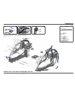
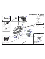
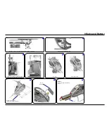
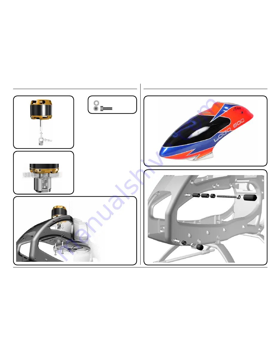
7 Mounting the Motor
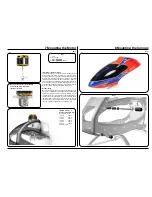
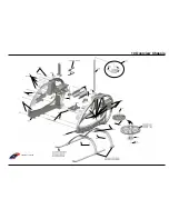
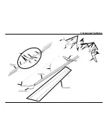
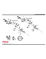
8 Mounting the Canopy
Bag 1
Bag 1
Installation of the Motor Pinion
Screw the motor pinion onto the motor shaft, making sure that
it can still be moved. Now mount the motor on the motor plate
and move the pinion so it is aligned well with the main gear.
As visual help for aligning the pinion you may use the small
ridge which separates the two parts of the pinion. When the
pinion is aligned correctly it will easily engage with the main
gear. If the pinion does not engage with the main gear, it is not
correctly aligned. After the pinion is correctly aligned, take the
motor out of the mainframe and tighten the set screw.
Gear Backlash
Move the motor with the pinion until it is limited by the gear.
Tighten one of the M4x14 screws slightly. You must still be able
to swivel the motor around its own axis. In this way you can
easily determine the correct distance between the main gear
and the pinion. There should be no (!) gear backlash. At the
same time, the motor should not (!) exert any pressure onto the
running surface of the main gear. After you have determined
the correct distance, tighten the second M4x14 screw.
Bag 1
available pinions for
module 1 diameter 6 mm
(not included in kit)
10 teeth*
#4410
11 teeth
#4411
12 teeth
#4412
13 teeth
#4413
14 teeth
#4414
15 teeth
#4415
*diameter 5 mm
For very hard 3d flying counterbearing
no. #4373 (30 mm, 6 mm shaft)
should be installed.
Bag 1


