6
SETTING UP GUN FOR ALUMINIUM WELDING
1. The Welding Gun
Remove the liner positioning nut from the adaptor block
at the wire feed end of the gun cable, remove the gas
nozzle, contact tip holder, gas diffuser/contact tip from
the welding torch and remove existing liner if fitted.
Carefully push the teflon liner through the gun cable until
the end of the liner protrudes from the swan neck and
withdraw the liner back into the swan neck.
Replace the contact tip holder, gas diffuser/contact tip
and gently push the liner to seat it into the back of the
contact tip holder/contact tip. Replace the gas nozzle.
At the adaptor block end of the gun cable, slide the brass
nipple a
nd ‘O’ ring over the liner until they are located in
the recess in the adaptor block and replace the liner
retaining nut.
DO NOT CUT THE TEFLON LINER YET!!!!
FIGURE 2.
2. The Welding Machine
With a pair of long nosed pliers, remove the steel inlet
guide tube from the central adaptor on the front face of
the welding machine.
With the teflon liner still protruding from the adaptor
block, feed the liner through the inlet of the central
adaptor until the adaptor block is butted against the
central adaptor. Fasten into position with adaptor block
lock nut.
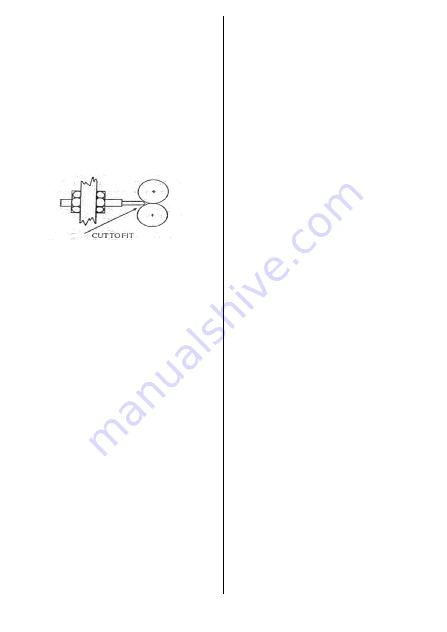
Cut the liner in the shape of a
‘V’, using a sharp knife so
that it butts up to the feed rollers as pictured. (FIG 2.)
Remove the welding gun from the machine and cut the
brass support tube so that it is 3mm shorter than the
protruding teflon liner.
Slide the brass support tube over the liner and enter the
teflon liner with brass support tube fitted into the inlet in
the central adaptor, feed through until the adaptor block
is butted against the central adaptor and tighten the lock
nut.
Reduce the wire hub tension by backing off the nut in the
centre of the hub until the nut is positioned at the end of
the stud.
After confirming the wire feed roll is correct size for the
aluminium wire being used, and that the wire is fed
through the gun cable, back off the wire feed roll
pressure screw until the feed roll no longer feeds the wire
and re-tighten approximately 2 turns. Too much
pressure will deform the soft aluminium wire and cause
the wire to jamb in the contact tip.
Note: To
help
prevent deformation, a
‘U’ groove feed roller is a
better alternative than a
‘V’ groove feed roller.
3. Contact Tip
Aluminium welding requires a contact tip with greater
clearance than that used for steel. Special clearance
contact tips are available for welding aluminium and are
designed with an A suffix. E.g. 0.9A, 1.2A.
PARTS LIST
PART NUMBER DESCRIPTION
1260005
Teflon Liner 1.0mm
1260021
Teflon Liner 1.2mm
1290461
Brass Support Tube for Teflon Liner
1310001
Nipple for Teflon Liner
86003020
Drive Roll 0.9/1.0-1.2mm Al
1410004
Contact Tip 0.9mm Aluminium
1410006
Contact Tip 1.0mm Aluminium
1410010
Contact Tip 1.2mm Aluminium
WELDING HINTS
Gasless Wire Welding (Flux Cored)
An optional Reverse Polarity Kit is available for gasless
welding wire requiring reverse polarity. When fitted, the
flexible welding cable extending from the front panel of
the machine should be plugged into the Negative
socket and the work lead into the Positive socket for
gasless wire welding.
For solid wire welding with Shielding Gas, simply
reverse these connections.
Gasless welding wire requires lower wire feed speeds
and voltage when compared to solid wires.
To ensure a positive wire feed, knurled feed rolls
appropriate to the wire size being used should be fitted
in place of smooth feed rolls.
Wire Size mm
0.8-1.0
Feed Roll Part #
86003016
Feed Roll Type
Smoo
th ‘V’
Wire Size mm
1.2-1.6
Feed Roll Part #
86003018
Feed Roll Type
Knurled
Aluminium Welding
Select a voltage setting approx. halfway through the
low range on your machine e.g.: 3-4 of 6 or 3-4 of 12.
Set the wire feed speed to approx. 20-25 litres per
minute when welding.
Remove oxide coating from weldments with a
stainless-steel wire brush. Initiate arc and lift the torch
nozzle away from the weld pool until the nozzle/weld
distance is 12-15 times the diameter of the wire e.g.:
11-14mm for 0.9mm wire. Direction of travel should be
from right to left by pushing the gun.
ALWAYS TEST SETTINGS ON A SCRAP PIECE OF
MATERIAL FIRST.
Stainless Steel Welding
Always use a clearance size liner e.g.: 1.2mm liner for
0.9mm wire. Wire and voltage feed settings will be
similar to those used for welding mild steel; however,
the different gas will increase the arc temperature.
Set the Gas Flow Meter to approx. 20 litres per minute.
Ensure when welding that the torch nozzle is lifted
away from the weld pool until the nozzle/weld pool
distance is 12-15 times the diameter of the wire. A
clearance size contact tip may be necessary in some
situations of high torch heat e.g.: 0.9Amm tip for 0.9mm
wire or 1.2Amm tip for 1.2mm wire.
Содержание 315PS
Страница 1: ...1 OPERATING MANUAL FOR MIGOMAG CLASSIC WELDING MACHINE 315PS ITEM AAC315PS ...
Страница 8: ...8 ...


