11135230-03
Installation
*INSTALLATION*
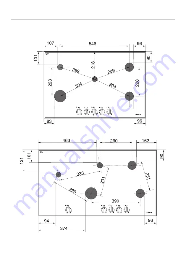
Distances from burner to the edge of the appliance
KM 3034-1
KM 3054-1
Страница 1: ...tant adhesive which will not dissolve or distort Any splashbacks must be of heat resistant material The cooktop must not be installed over a fridge fridge freezer freezer dishwasher washing machine washer dryer or tumble dryer A gas cooktop must not be installed directly next to a deep fat fryer as the gas flames could ignite the fat in the fryer It is essential to maintain a distance of at least ...
Страница 2: ...f the manufacturer s instructions are not available for the rangehood a minimum safety distance as per AS NZS 5601 1 must be maintained For any flammable objects e g utensil rails wall units etc a minimum safety distance of 600 mm must be maintained between these objects and the highest part of the cooktop below When two or more appliances which have different safety distances are installed togeth...
Страница 3: ...he rear and a tall unit or wall on one side right or left On the other side however no tall unit or wall should stand higher than the appliance Before installing the appliance check that the location provides the required clearances from combustible material and if necessary provide protection to adjacent surfaces as required by regulations Not allowed Recommended Not recommended Not recommended ...
Страница 4: ...dge of the nearest burner for the full dimension of the cooktop depth width X Height from worktop surface to the top of the edge of the burner The shown area indicates the protected surface which may be ceramic tiles or other approved material Combustible surface A material which will ignite and burn and includes material which has been flameproofed Clearance underneath the appliance A minimum saf...
Страница 5: ...INSTALLATION Detailed dimensions Height of pan supports above the worktop surface a Vertical distance b Worktop surface c Pan support The vertical distance from the top of the pan supports to the surface of the worktop is 57 mm ...
Страница 6: ...11135230 03 Installation INSTALLATION Distances from burner to the edge of the appliance KM 3034 1 KM 3054 1 ...
Страница 7: ...s to be removed for servicing Do not use sealant between the cooktop and the worktop The sealing strip under the edge of the cooktop provides a sufficient seal for the worktop Tiled worktop Grout lines and the hatched area underneath the cooktop frame must be smooth and even If they are not the cooktop will not sit flush with the worktop and the sealing strip underneath the cooktop will not provid...
Страница 8: ... dimensions All dimensions in this instruction booklet are given in mm KM 3034 1 a Front b Building in depth c Mains connection box with mains connection cable L 2 000 mm d Gas connection R ISO 7 1 e Electronics housing maximum building in depth 78 mm ...
Страница 9: ... 03 Installation INSTALLATION KM 3054 1 a Front b Building in depth c Mains connection box with mains connection cable L 2 000 mm d Gas connection R ISO 7 1 e Electronics housing maximum building in depth 78 mm ...
Страница 10: ... between the frame and worktop will become smaller over time Installing the cooktop Attach the sealing strip provided underneath the edge of the cooktop Feed the mains connection cable down through the worktop cut out Place the cooktop centrally in the cut out When doing this make sure that the seal of the appliance sits flush with the worktop on all sides This is important to ensure an effective ...
Страница 11: ...Checking operation After installing the cooktop ignite all burners to check that they are operating correctly The flame must not go out on the lowest setting or when the control is turned quickly from the highest to the lowest setting On the highest setting the flame must have a distinctive and visible core ...
Страница 12: ...lled so that connection can be made either from inside or outside the kitchen furniture unit Every appliance must have its own isolating valve The isolating valve must be easily accessible and visible by opening the cabinet door if necessary Check with your local gas supplier about the type of gas supplied and compare this information with the type of gas quoted on the appliance s data plate The c...
Страница 13: ...ry of destination this appliance is set up for connection to natural gas or ULPG See adhesive label on the appliance G NG natural gas LP ULPG Propane Butane Depending on country of destination jets are supplied for conversion to a different type of gas If the appropriate jets have not been supplied with the appliance you will need to contact Miele Conversion to another type of gas is described in ...
Страница 14: ... increase to the depth of the elbow used For natural gas models The gas regulator is only included with appliances which are set up for connection to natural gas The regulator must be connected directly to the appliance a a Pressure Test Point Loosen the screw in the test point until it is free in its housing The screw is retained in this position Connect the hose from the pressure gauge Reassembl...
Страница 15: ... Nominal ratings Burner Gas type Highest setting Lowest setting MJ h MJ h Auxiliary burner NG ULPG 4 0 3 2 1 0 0 6 Semi rapid burner NG ULPG 6 0 5 5 1 0 1 3 Rapid burner NG ULPG 9 8 8 1 1 6 2 1 Wok burner NG ULPG 17 0 14 6 1 8 1 6 Total NG ULPG 42 8 36 9 ...
Страница 16: ...provided for all poles in accordance with the wiring rules When switched off there must be an all pole contact gap of at least 3 mm in the switch including switch fuses and relays Connection data is shown on the data plate It must match the mains electrical supply After installation ensure that all electrical components are shielded and cannot be accessed by users Total power output See data plate...
Страница 17: ...ce with current local and national safety and building regulations The installer is responsible for ensuring that the appliance functions correctly when installed Disconnect the cooktop from the electricity supply and turn off the gas supply Jet table The jet markings refer to a mm bore diameter Main jet Small jet NG Auxiliary burner 0 90 0 52 Semi rapid burner 1 10 0 52 Rapid burner 1 43 0 60 Wok...
Страница 18: ...main jets Auxiliary semi rapid and rapid burners Remove the pan support burner cap and burner head Using an M7 socket spanner unscrew the main jet Fit the correct jets securely see jet table Secure the jets against inadvertent loosening with sealing wax Wok burner Remove the burner cap and burner head Using an M7 socket spanner unscrew the main jets Fit the correct jets securely see jet table Secu...
Страница 19: ... upper section of the appliance removed Pull the control knobs off Remove the burner components Lift the top of the appliance off see illustration Using a small screwdriver unscrew the small jet in the gas fitting Pull out the jet with a pair of pliers Fit the correct jets securely see jet table Secure the jets against inadvertent loosening with sealing wax ...
Страница 20: ...l burners to check that they are operating correctly The flame must not go out on the lowest setting or when the control is turned quickly from the highest to the lowest setting On the highest setting the flame must have a distinctive and visible core Adhere the label supplied with the jets over the old label stating the type of gas being used ...