


Technical Information
83
DGC 6xxx
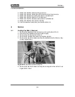
Figure 045-9:
Feed Pump
4.4
Fascia Panel Position Switch (S60) Removal
1. Remove the appliance from its housing unit; see Section 010-4.1.
2. Disconnect the appliance from the power supply.
3. Remove the lid; see Section 010-4.2.
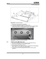
4. Remove the two Phillips screws securing the position switch (Figure 045-
10, Item 1).
Figure 045-10:
Position Switch Screws
5. Disconnect the electrical connections from the switch.
4.5
Water Container Switch (B3-17, B3-18, B3-19) Removal
Note:
The water tank switches (B3-17 and B3-18) are part of one assembly and
must be replaced together.
1. Remove the appliance from its housing unit; see Section 010-4.1.
2. Disconnect the appliance from the power supply.
3. Remove the lid; see Section 010-4.2.
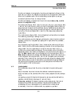
4. Unclip the appropriate switch(es) from the water container; see Figure
045-11, Item 1.
5. Disconnect the switch(es) from the power electronic.
1
2
2
3
Содержание DGC 6 Series
Страница 1: ...TECHNICAL INFORMATION DGC 6xxx Combi Steam Ovens 2018 Miele USA ...
Страница 15: ...Technical Information 15 DGC 6xxx 010 Casing ...
Страница 23: ...Technical Information 23 DGC 6xxx 020 Door ...
Страница 27: ...Technical Information 27 DGC 6xxx 030 Cavity ...
Страница 43: ...Technical Information 43 DGC 6xxx 035 Steam Generator Convection Fan ...
Страница 57: ...Technical Information 57 DGC 6xxx Figure 035 14 Terminal Block ...
Страница 58: ...Technical Information 58 DGC 6xxx 040 Water Container Drive ...
Страница 68: ...Technical Information 68 DGC 6xxx 045 Air Duct Power Electronic ...


