Midland MICRO MOBILE MXT500 Скачать руководство пользователя страница 13

Page 13

midlandusa.com

Model MXT500

OPERATING YOUR RADIO

About Range

Your MXT500 is designed to give you maximum operating range under 
optimal conditions.

Optimal conditions for maximum operating range are:

     • Over water

     • In open rural areas without obstructions

‡2QÀDWDUHDVZKHUH\RXFDQVHHWKHRWKHUUDGLRXVHU

To ensure you get maximum range: 

• Be sure to mount the antenna (sold separately) as high as possible on  
  your vehicle

• Be sure to set your radio to use Hi power (see Selecting the Transmit  
   (TX) Power Level)

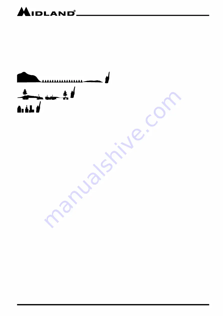
Maximum Range / No Sight Obstruction

Medium Range / Partial Obstruction to Line of Sight

Short Range / Major Obstruction to Line of Sight

Содержание MICRO MOBILE MXT500

Страница 1: ......

Страница 2: ...g the Volume 14 Transmit and Receiving a Call 15 UTILITY FUNCTIONS 15 Locking the Keypad 15 Using Monitor Mode 15 Scanning for Active Channels 17 Using Scan Skip 17 CallAlert 18 Menu Functions 18 MENU MODE FUNCTIONS 19 Selecting a Privacy Code 19 Selecting the Transmit TX Power Level 21 Selecting a Channels Bandwidth 22 Automatic Power Off Function 24 Squelch Sensitivity 24 Display Color 25 Displa...

Страница 3: ...uit board Your MXT500 radio is designed for reliability and trouble free performance for years to come FEATURES 50 Watt GMRS Radio 15 GMRS Channels 8 Repeater Channels Split Privacy Tones Water Resistant IPX6 NOAA Weather Radio Narrow and Wide Band 142 Privacy Codes 38 CTCSS 104 DCS Monitor Function Keypad Lock Talk Around Function Automatic Power Off Function Adjustable Color and Brightness Setti...

Страница 4: ...th Part 15 of the FCC rules Operation is subject to the condition that this device does not cause harmful interference Exposure To Radio Frequency Energy Your Midland radio is designed to comply with the following national and international standards and guidelines regarding exposure of human beings to radio frequency electromagnetic energy United States Federal Communications Commission Code of F...

Страница 5: ...in your vehicle s Service Manual Make sure all necessary tools materials and parts are on hand Disconnect the negative battery cable before installing your radio Be sure to reconnect the cable when installation is complete Determine a mounting location for your radio Choose a location that does not impair visibility or interfere with driving Also take into consideration the routing and length of t...

Страница 6: ...the hole locations 2 Attach the bracket to the dash with the Phillips head sheet metal screws provided Tighten the screws securely DO NOT OVER TIGHTEN 3 Once the bracket is secured to the vehicle slide the radio into the bracket Be sure the radio locks into the bracket so it does not shift while the vehicle is in motion INSTALLING THE MOUNTING BRACKET 3 I OLAN r _____________ 0 ...

Страница 7: ...igher the better 3 If possible mount the antenna in the center of whatever surface you choose 4 The antenna cable is 19 7 feet 6 meters long Be sure the mounting location will allow for connection of the cable to the radio 5 Be sure the mounting location is clean and dry before installing the antenna 6 Route the antenna cable through an accessible entry point such as a rear door or trunk opening 7...

Страница 8: ...The microphone mounting bracket can be attached to the vehicle dash or other convenient location in a manner similar to the radio s mounting bracket USING AN EXTERNAL SPEAKER The MXT500 provides a rear panel jack for connection of an optional external speaker sold separately The rear panel jack is compatible with 3 5mm audio connector When selecting an external speaker ensure the speaker has 8 ohm...

Страница 9: ...b 2 Speaker Mic Jack 3 Menu Button 4 Scan Scan Skip Button 5 Monitor Button 6 WX Button 7 Lock Button 8 Power Indicator 9 TX RX Indicator 10 Channel Menu Selection Knob 11 USB C Port 1 3 4 5 6 7 11 10 9 2 8 Jl1DLAND _____________ E ANr J El Mi o NarA 0 tIJ SQ DCSOTi DJ WX ml 50 5 CH rr MENU SCAN MON WX LOCK ...

Страница 10: ...Page 10 midlandusa com Model MXT500 MICROPHONE OPERATING CONTROLS 1 Channel Down 2 Channel Up 3 PTT 4 Microphone 1 3 4 2 I OLAN r _____________ c c 0 c I c I c c DN UP c c ...

Страница 11: ...Page 11 midlandusa com Model MXT500 REAR PANEL CONNECTIONS 1 Antenna Jack 2 Intecom jack 3 External Speaker jack 1 3 2 Jl1DLAND _____________ ...

Страница 12: ...nd Channel 5 Auto power off 6 Repeater offset direction 7 Scan Indicator 8 CTCSS Privacy Tone 9 DCS Privacy Tone 10 Key Lock 11 Weather band 12 Channel Icon 13 Menu item indicator 14 Receive indicator 15 Receive and transmit signal strength 12 13 2 3 4 5 7 9 10 11 I OLAN r _____________ ...

Страница 13: ...areas without obstructions 2Q ÀDW DUHDV ZKHUH RX FDQ VHH WKH RWKHU UDGLR XVHU To ensure you get maximum range Be sure to mount the antenna sold separately as high as possible on your vehicle Be sure to set your radio to use Hi power see Selecting the Transmit TX Power Level Maximum Range No Sight Obstruction Medium Range Partial Obstruction to Line of Sight Short Range Major Obstruction to Line of...

Страница 14: ... THE ACTIVE CHANNEL IMPORTANT To communicate between two MXT500 radios or any GMRS radio both radios must be set to the same channel and privacy code see Selecting a Privacy Code selections 1 Rotate the CHANNEL MENU SELECTION knob clockwise to scroll forward through the available channels Rotate the CHANNEL MENU SELECTION knob counterclockwise to scroll backward through the available channels The ...

Страница 15: ...your radio is transmitting The signal strength indicator on the LCD will display the transmit signal strength 2 To receive a call release the PTT button on the microphone The BUSY icon will show on the LCD display when your radio is receiving a transmission The TX RX indicator will illuminate green when your radio is receiving The signal strength indicator on the LCD will display the signal streng...

Страница 16: ...l play to notify you that the radio is locked 1 To lock press and hold the LOCK button The KEY LOCK icon will display on the LCD when the radio is locked 2 To unlock press and hold the LOCK button The KEY LOCK icon will disappear on the LCD when the radio is unlocked USING MONITOR MODE Monitor mode lets you check for activity on the current active channel You can also use Monitor mode to adjust th...

Страница 17: ...e seconds after the PTT button is released 3 To exit auto scan mode press the SCAN button NOTE If you transmit during auto scan and the auto scan has not found and active channel it will transmit on the last selected channel USING SCAN SKIP 6FDQ VNLS DOORZV RX WR RSW RXW RI VFDQQLQJ VSHFL F FKDQQHOV ZKHQ XVLQJ auto scan 1 Before using scan skip be sure the radio is powered on see POWER ON OFF 2 Se...

Страница 18: ... alert press and hold the PTT button While pressing and holding the PTT button press the UP button on the microphone The call tone will transmit The bottom LED will illuminate red while your radio is transmitting the call alert The signal strength indicator on the LCD will display the call alert signal strength 2 To disable the call alert press the PTT MENU FUNCTIONS 0HQX IXQFWLRQV OHW RX FRQ JXUH...

Страница 19: ...any channel If desired you can select a different Privacy Code for each channel See CTCSS Privacy Codes Frequency Chart and DCS Privacy Codes Chart for lists of available Privacy Codes IMPORTANT To communicate between two MXT500 radios or any GMRS radio both radios must be set to the same channel see SELECTING AN ACTIVE CHANNEL and privacy code selections 1 Press the MENU button to enter the menu ...

Страница 20: ...ting See CTCSS PRIVACY CODE CHART 4 Repeat steps 2 3 for transmit privacy code TRP 5 Press the menu button to exit the privacy code settings To Select a DCS Privacy Code The MXT500 has 104 DCS privacy codes 1 Follow steps 1 3 under SELECTING A PRIVACY CODE 2 For receive privacy code RCP select DCS in the privacy menu by pressing the CHANNEL MENU SELECTION knob 3 Use the CHANNEL MENU Selection to n...

Страница 21: ... transmit power levels Hi Mi and Lo The Lo power level is generally suitable when operating under optimum conditions see ABOUT RANGE The Hi power level is recommended to ensure you get maximum range from your radio IMPORTANT Channels 1 7 cannot be removed from the Lo transmit power setting due to power output regulations 1 Press the MENU button to enter the menu Use the CHANNEL MENU SELECTION knob...

Страница 22: ...o menu setting 03 NB narrow band 2 To edit the channel bandwidth press the CHANNEL MENU SELECTION knob Use the CHANNEL MENU SELECTION knob to choose between NB narrow band ON or OFF Press the CHANNEL MENU 6 7 21 NQRE WR FRQ UP RXU VHOHFWLRQ NB ON is selecting narrow band NB OFF is selecting wide band Only the NB narrow band will be indicated on the LCD When the NB is not displayed it indicates the...

Страница 23: ...le or disable to voice compander function press the CHANNEL MENU SELECTION knob Use the CHANNEL MENU SELECTION knob to choose between ON or OF Press the CHANNEL MENU 6 7 21 NQRE WR FRQ UP RXU VHOHFWLRQ Once the voice compander is enable the D icon will appear on the LCD If the voice compander is disabled the D icon will disappear 3 Press the menu button to exit the voice compander settings Silent ...

Страница 24: ...r off after no use 1 Press the MENU button to enter the menu Use the CHANNEL MENU SELECTION knob to navigate to menu setting 08 APO 2 To set the automatic power off press the CHANNEL MENU SELECTION knob Use the CHANNEL MENU SELECTION knob to choose between OFF 30 60 90 120 minutes Press the CHANNEL 0 18 6 7 21 NQRE WR FRQ UP RXU VHOHFWLRQ Once the automatic power off function is enabled the A icon...

Страница 25: ...nob Use the CHANNEL MENU SELECTION knob to choose between GRN LU CYN YEL PUR CLR and RED Press the CHANNEL MENU 6 7 21 NQRE WR FRQ UP RXU VHOHFWLRQ You can preview each color while navigating the menu options 2QFH RX FRQ UP RXU FRORU VHOHFWLRQ WKH ZLOO GLVSOD WKH FRORU chosen 3 Press the menu button to exit the LCD color settings Display Brightness You can adjust the six brightness levels of the L...

Страница 26: ...FRQ UP RXU VHOHFWLRQ Once repeater channels are enabled they will be available in the channel list see SELECTING AN ACTIVE CHANNEL They will be displayed as RP 15 RP 22 When using a repeater channel a will appear on the LCD to indicate the repeater offset direction 3 Press the menu button to exit the repeater channel settings USB C Programming Function The MXT500 had a built in USB C charging port...

Страница 27: ...the factory default settings for your MXT500 at any time 1 Press the MENU button to enter the menu Use the CHANNEL MENU SELECTION knob to navigate to menu setting 14 RESTORE 2 To reset your radio press the CHANNEL MENU SELECTION knob Use the CHANNEL MENU SELECTION knob to select FACT Press the 11 0 18 6 7 21 NQRE WR FRQ UP RXU VHOHFWLRQ 3 Once reset the radio will restart with the factory settings...

Страница 28: ... unit for service PROBLEM No Power Cannot Receive Messages Check vehicle power source battery replace as needed Check input power connection and or wires to vehicle power source Verify both radios have the same channel selection and Privacy Code settings RQ UP FRPPXQLFDWLRQ LV QRW DIIHFWHG E EXLOGLQJV and other structures see About Range Make sure keypad lock is not on see Locking the Keypad RQ UP...

Страница 29: ...annels 38 CTCSS 104 DCS UHF 462 5500 462 725 MHz UHF 462 5625 467 725 MHz 13 8 VDC Nominal Rcp tsq Rcp off rcp dcs 001 104 trp tsq 67 0 250 3 trp dcs trp off 67 0 250 3 001 104 0 18 privacy pwr nb talk comp mute tot lo mi hi Off on Of on Of on Of on Off 300 apo Off on sql col lamp call usb restore Of 09 Of 05 Off on Red grn blu cyn yel pur clr Off on fact rep Of 06 IDLANd _____________ ...

Страница 30: ...RP 467 6750 462 6750 21RP 467 7000 462 7000 22RP 467 7250 462 7250 GMRS REPEATER FREQUENCY CHART MHz GMRS FREQUENCY CHART MHz 1 462 5625 15 462 550 2 462 5875 16 462 575 3 462 6125 17 62 600 5 462 6625 19 462 650 6 462 6875 20 462 675 7 462 7125 21 462 700 22 462 725 4 462 6375 18 462 625 CH 8 14 Restricted to Portable Use Only Ch No Ch No Ch Freq MHz Ch Freq MHz Jl1DLAND _____________ ...

Страница 31: ... 16 115 42 311 68 612 94 274 17 116 43 315 69 624 95 325 18 125 44 331 70 627 96 332 19 131 45 343 71 631 97 356 20 132 46 346 72 632 98 446 21 134 47 351 73 654 99 452 22 143 48 364 74 662 100 454 23 152 49 365 75 664 101 455 24 155 50 371 76 703 102 462 25 156 51 411 77 712 103 523 26 162 52 412 78 723 104 526 3 74 4 11 97 4 19 127 3 27 167 9 35 225 7 9 2 71 9 10 8 18 123 0 26 162 2 34 218 1 4 4...

Страница 32: ...on against harmful interference in a residential installation This equipment generates uses and can radiate radio frequency energy and if not installed and used in accordance with the instructions may cause harmful interference to radio communications However there is no guarantee that interference will not occur in a particular installation If this equipment does cause harmful interference to rad...

Страница 33: ...Y INJURY PROPERTY DAMAGE AND DEATH FOR DAMAGES IN EXCESS OF THE PURCHASE PRICE OF THE PRODUCT OR ACCESSORY OR FOR ANY INDIRECT INCIDENTAL SPECIAL OR CONSEQUENTIAL DAMAGES OF ANY KIND OR LOSS OF REVENUE OR PROFITS LOSS OF BUSINESS LOSS OF INFORMATION OR DATA OR OTHER FINANCIAL LOSS ARISING OUT OF OR IN CONNECTION WITH THE ABILITY OR INABILITY TO USE THE PRODUCTS OR ACCESSORIES TO THE FULL EXTENT TH...

Страница 34: ...component crystal semiconductor etc not authorized by the FCC equipment authorization for this radio could violate FCC rules Note Use of this radio outside the country where it was intended to be distributed is subject to government regulations and may be prohibited Important Any changes or modifications not expressly approved by the party responsible for compliance could void the user s authority...

Страница 35: ...TION is not responsible for unintentional errors or omissions on its packaging We d love to hear from you Let us know what you think of your new Midland product at or by visiting us at midlandusa com MIDLAND RADIO CORPORATION 5900 Parretta Drive Kansas City MO 64120 Call 816 241 8500 IDLAND ...

Отзывы: