background image

Model DBR2500

page 31

midlandusa.com


The selected COM Port may be different, even on the same computer, when the USB 
Cable is connected to a different USB Port.

4� According to the instructions, select the correct ”COM Port”, then click “OK” to start the 
programming software�

Make sure the DBR2500 is powered on prior to writing any data to the radio� 

Do not turn off the DBR2500 while it is connected to the computer. Doing so will cause the 

DBR2500 to disconnect from the computer, thus not allowing the computer to read/write to the 
DBR2500� 

If the DBR2500 is disconnected from the computer, close the programming software, pull out 
the USB cable, then reinsert the USB cable and re-open the programming software� Then re-
select the COM Port and the DBR2500 will resume normal operation� 

MAINTENANCE
Factory Default Settings

Frequency band

VHF

UHF

VFO frequency

144�000MHz

450�000MHz

Memory channel

--

--

Offset direction

--

--

Offset frequency

600KHz

5MHz

Chanel step

10KHz

10KHz

CTCSS encode & decode

--

--

CTCSS tone frequency

88�5Hz

88�5Hz

DCS encode & decode

--

--

DCS Code

000N

000N

Output power

HI

HI

TOT

3

3

APO

OFF

OFF

VOL

28

28

Squelch level

3

3

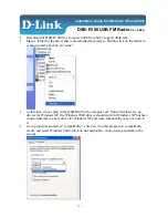
3� Double click the “DBR2500” appliation shortcut or click DBR2500 from the start menu, 
choose “Serial Com Port” as indicated then click “OK” to start programming software

Содержание DBR2500

Страница 1: ......

Страница 2: ...lay 13 Microphone 14 OPERATING YOUR RADIO 15 VFO or Channel Mode 15 BASIC OPERATIONS 16 Switching the power On Off 16 Adjusting the Volume 16 Adjusting Frequency 16 Adjusting the Channel 16 Receiving 17 Transmitting 17 Switch between Main Channel and Sub Channel 17 Switch between VFO and Channel Mode 17 Channel Edit 17 Channel Delete 18 CTCSS DCS Encode and Decode Setup 18 CTCSS Scan 19 DCS Scan 1...

Страница 3: ...Optional Signaling 26 Signaling Combination Setup 27 Bandwidth Selection 27 Frequency Reverse 27 Talk Around 27 Offset Frequency and Direction Setup 28 Editing Channel Name 28 Busy Channel Lockout 28 Transmit TX Off 29 OWNID Self ID Inquiry 29 Main Unit Keypad Menu Setup 29 H DIM Microphone Keypad Backlight Setup 29 Micrphone Keypad Backlight Brightness Setup 29 H PA H PD Micrphone Self Define Key...

Страница 4: ...ne key lock function 5Tone signaling for data transfer alarm all call ANI remote kill and remote wake DTMF ANI or 5Tone ANI for automatic call recognition FCC NOTICE This equipment has been tested and found to comply with the limits for a Class B digital device pursuant to part 15 of the FCC Rules These limits are designed to provide reasonable protection against harmful interference in a resident...

Страница 5: ... permissible transmissions only avoiding channel interference with other HAM users and being prudent with the length of your transmission time To obtain a license or ask questions about the application contact the FCC at 1 888 CALL FCC or go to the FCC s website http www fcc gov and request form 605 Exposure To Radio Frequency Energy Your Midland radio is designed to comply with the following nati...

Страница 6: ...er select a safe convenient location inside your vehicle that minimizes danger to your passengers and yourself while the vehicle is in motion Consider installing the unit at an appropriate position so that knees or legs will not strike it during sudden braking of your vehicle Try to select a well ventilated location that is shielded from direct sunlight Also take into consideration the routing and...

Страница 7: ...ected from heat moisture and engine secondary high voltage ignition system and cables 2 After installing the DC power cable to avoid the risk of damage please use heat resistant tape to tie together the DC power cable with the fuse box Be sure to reinforce the entire power cable with heat resistant tape 3 In order to avoid the risk of a short circuit please disconnect the connection with the negat...

Страница 8: ...DBR2500 to a regulated power supply Do not substitute a cable with smaller gauge wires 2 Connect the DBR2500 s DC power connector to the connector on the DC power cable Press the connectors firmly together until the locking tab clicks Before connecting the DC power to the DBR2500 be sure to switch the transeiver and the DC power supply to OFF Do not plug the DC power supply into an AC outlet until...

Страница 9: ...ces the efficiency of the antenna system and can cause interference to nearby broadcast television receivers radio receivers and other electronic equipment Transmitting without first connecting an antenna or other matched load may damage the DBR2500 Always connect the antenna to the DBR2500 prior to transmitting All fixed stations should be equipped with a lightning arrester to reduce the risk of ...

Страница 10: ...rnal speaker utilizes a double port BTL please take care when connecting a speaker to this port Do not allow the speaker to make contact with a ground as it could damage the speaker The image on page 11 shows the incorrect connecting method 6 When routing the antenna cable inside the vehicle keep the cable away from noise sources such as the ignition system gauges etc 7 Exercise care to prevent ca...

Страница 11: ...el DBR2500 page 11 midlandusa com Microphone Insert the 8P8C commonly RJ45 connector into the front of the DBR2500 Press firmly on the plug until the locking tab clicks CONTROLS AND INDICATORS Front Panel ...

Страница 12: ...Function button Function group button 9 User programmable button also referred to as a P X button 10 Channel switch Push button Key lock 11 User programmable button also referred to as a P X button No Feature Function 1 Ex Speaker Jack Connect an optional external speaker 2 Power Cable Connect a standard DC power cable 3 Antenna Connector Connect a 50 ohm antenna The term P X button is used in ref...

Страница 13: ... channel mode 8 Displays main channel frequency or name 9 Displays subchannel number in channel mode 10 Displays the main channel TX or RX status 11 Displays when automatic power off function is on 12 Displays when setting the band width for main channel 13 Displays when setting the main channel CTCSS DCS 14 Displays the main channel field strength 15 Displays when main channel reverse function is...

Страница 14: ... here during transmission 6 A B Band Choose left band or right band as main band 7 Number Key Input VFO frequency or DTMF dial out etc 8 Band Indicator The indicator light on for the main band 9 Speaker If base unit speaker is off sound will only emit from handset speaker 10 PTT Press the PTT Push to Talk key to transmit 21 Displays when sub channel reverse function is on 22 Displays when sub chan...

Страница 15: ...orarily used by the user Once the radio is turned off or switched to another channel the temporary setting will be erased and will revert back to the initial settings shown in pic 1 b Channel Name Tag Mode When setting the display as NM it enters into Channel Name Tag mode In this mode it will display corresponding channel name when the current channel is edited with a name Otherwise it will displ...

Страница 16: ...djust the frequency each press will move one step size Hold the button down to speed up the frequency adjustment If the channel knob is programmed as VOL function users need to press the P X button which is programmed as FRQ function when the LCD displays VFO FREQ turn the channel knob to adjust the frequency 2 Using the number buttons in VFO mode you can input the desired frequency by using the m...

Страница 17: ...s and release the FUNC button to switch function group choose the P X button defined as A B function 2 Press and release the P X button defined as A B function then repeat press the P X button or turn the channel knob to switch the main channel and sub channel the LCD will display Main XX 3 Hold the PUSH button or the FUNC button to store and exit or wait 10 seconds for the radio to store the sett...

Страница 18: ...Press and release the P X button defined as CDT function then repeatedly short press this button to set the current channel if using a CTCSS DCS to encode and decode 3 When the LCD displays RCDT XXX turn the channel knob or press the microphone UP DOWN button to choose to add CTCSS DCS decode signaling to current channel Press the PUSH button then turn channel knob or press the microphone UP DOWN ...

Страница 19: ... designed to monitor signal of all frequency points under each step size 1 In VFO mode press and release the FUNC button to switch the function group choose the P X button defined as SCN function 2 Press and release the P X button defined as SCN function to start frequency scan the LCD displays S 3 Turn channel knob or press microphone UP DOWN button to change scan direction 4 Turn channel knob or...

Страница 20: ...he keypad is locked 2 Press and hold PUSH button again the lower part of the LCD displays Key Unlock means the keypad is unlocked When the keypad is locked the button PUSH button and PTT button will continue to remain operational Transmit DTMF 5 Tone Signaling If the current channel requires DTMF 5 Tone signaling hold the PTT button and the UP button to transmit pre programmed DTMF 5 Tone signalin...

Страница 21: ...en 3 Turn the channel knob to choose the desired setting FRQ Frequency Channel mode VFO mode CH Channel mode NM Channel name mode Channel mode VFO mode If the channel is not named it will display Frequency Channel mode otherwise it displays the channel name VFO mode 4 Press the PUSH button or P3 button to store the setting and exit Squelch Level Setup This function is used for setting the RX signa...

Страница 22: ...once when scanning for a matching signal and resumes scanning when the signal disappears SE it stops once scanning receives a matching signal 4 Press the PUSH button or P3 button to store the setting and exit Scan Pause Time Setup 1 Enter the FUNCTION MENU list choose the No 08 function 2 Press the PUSH button the menu value in the LCD turns to green 3 Turn the channel knob to choose the desired s...

Страница 23: ...the PUSH button the menu value in the LCD turns to green 3 Turn the channel knob to choose the desired setting 1 30 1 30 minutes range available by 1 minute step OFF Turn off the TOT function 4 Press the PUSH button or P3 button to store the setting and exit APO Automatic Power Off Once APO is activated the transceiver will automatically be switched off when the pre set timer runs out 1 Enter the ...

Страница 24: ...one speaker MAIN Turn on Main speaker HAND Turn on microphone speaker 4 Press the PUSH button or the P3 button to store the setting and exit RTDF RX TX Dissimilar Frequency Setup The DBR2500 has dissimilar frequency function when this function is on the frequency on the top portion of the LCD is the RX frequency and the frequency on the bottom is the TX frequency You can change the RX frequency by...

Страница 25: ...S DCS Decode Setup 1 Enter the CHAN MENU choose the No 1 function 2 Press the PUSH button the menu value in the LCD turns to green 3 Turn the channel knob to choose the desired setting OFF Turn off CTCSS DCS decode CTCSS Choose CTCSS decode DCS Choose DCS decode 4 When selecting CTCSS DCS decode press the PUSH button to enter CTCSS DCS decode setup then turn the channel knob to choose the desired ...

Страница 26: ... setting 0 99 Total of 100 groups 5Tone encode for selection 4 Press the PUSH button or the P3 button to store the setting and exit 5 Tone group name and connect shall be programmed by PC software If the selected 5Tone encoding has a group name the LCD will display group name only T DEC Add Optional Signaling This transceiver has 2 optional signaling modes DTMF 5Tone Those signaling modes function...

Страница 27: ... choose the No 7 function 2 Press the PUSH button the menu value in the LCD turns to green 3 Turn the channel knob to choose the desired setting WID band width is 25k Wide band MID band width is 20k Middle band NAR band width is 12 5k Narrow band 4 Press the PUSH button or the P3 button to store the setting and exit Frequency Reverse With this function on the transceiver will be able to communicat...

Страница 28: ...the PUSH button the menu value in the LCD turns to green 3 Turn the channel knob to choose the desired setting Press the PUSH to confirm and enter editing for the next charactor 4 Press the PUSH button or the P3 button to store the setting and exit Busy Channel Lockout Busy channel lockout is to disable transmitting once the channel is busy and you press the PTT the radio will beep as warning and ...

Страница 29: ... Press and release the P1 P6 button to choose the desired self define button 7 Press the FUNC buttonto confirm and exit H DIM Microphone Keypad Backlight Setup 1 Hold the FUNC button to enter the SELECT MENU interface 2 Press and release the P4 button P6 button or turn the channel knob to select menu list Press and release the P5 button to quickly turn the page 3 Press the PUSH button to enter the...

Страница 30: ...to store the setting and exit DTMF Encoding Transmitting Time 1 Enter the DTMF menu Choose the No 2 function 2 Press the PUSH button the menu value in the LCD turns to green 3 Turn the channel knob to choose the desired setting 50MS The time for transmit a single DTMF encode and the interval is 50MS 100MS The time for transmit a single DTMF encode and the interval is 100MS 200MS The time for trans...

Страница 31: ... DBR2500 is disconnected from the computer close the programming software pull out the USB cable then reinsert the USB cable and re open the programming software Then re select the COM Port and the DBR2500 will resume normal operation MAINTENANCE Factory Default Settings Frequency band VHF UHF VFO frequency 144 000MHz 450 000MHz Memory channel Offset direction Offset frequency 600KHz 5MHz Chanel s...

Страница 32: ...quelch is active Turn CTCSS or DCS squelch off 5 Key and Dial do not function Key lock function is activated Cancel Key lock function 6 No Scan Did not list the channel in the scan when programmed The whole band with noise after programmed The squelch has opened during programmed Communication range was short bad sensitivity a Check the antenna is well or not and check the antenna port whether wel...

Страница 33: ...Model DBR2500 page 33 midlandusa com SPECIFICATIONS ...

Страница 34: ...3 35 179 9 46 225 7 3 69 3 14 100 0 25 146 2 36 183 5 47 229 1 4 71 9 15 103 5 26 151 4 37 196 2 48 233 6 5 74 4 16 107 2 27 156 7 38 189 9 49 241 8 6 77 17 110 9 28 159 8 39 192 8 50 250 3 7 79 7 18 114 8 29 162 2 40 196 6 51 254 1 8 82 5 19 118 8 30 165 5 41 199 5 52 user defined 9 85 4 20 123 0 31 167 9 42 203 5 10 88 5 21 127 3 32 171 3 43 206 5 11 91 5 22 131 8 33 173 8 44 210 7 ...

Страница 35: ...38 211 139 212 140 213 141 214 142 215 143 216 144 217 145 220 146 221 147 222 148 223 149 224 150 225 151 226 152 227 153 230 154 231 155 232 156 233 157 234 158 235 159 236 160 237 161 240 162 241 163 242 164 243 165 244 166 245 167 246 168 247 169 250 170 251 171 252 172 253 173 254 174 255 175 256 176 257 177 260 178 261 179 262 180 263 181 264 182 265 183 266 184 267 185 270 186 271 187 272 1...

Страница 36: ...398 615 399 616 400 617 401 620 402 621 403 622 404 623 405 624 406 625 407 626 408 627 409 630 410 631 411 632 412 633 413 634 414 635 415 636 416 637 417 640 418 641 419 642 420 643 421 644 422 645 423 646 424 647 425 650 426 651 427 652 428 653 429 654 430 655 431 656 432 657 433 660 434 661 435 662 436 663 437 664 438 665 439 666 440 667 441 670 442 671 443 672 444 673 445 674 446 675 447 676 ...

Страница 37: ...must accept any interference thay may cause undesired operations FCC WARNINGS AND STATEMENTS IMPORTANT MIDLAND RADIO CORPORATION makes no warranty or claim regarding any modification to your DBR2500 not fully authorized by MIDLAND RADIO CORPORATION nor any change in operability performance or regulatory compliance arising therefrom You are solely responsible for operating your DBR2500 in accordanc...

Страница 38: ...N LIEU OF ALL OTHER WARRANTIES EXPRESS OR IMPLIED IN NO EVENT SHALL MIDLAND BE LIABLE WHETHER IN CONTRACT OR TORT INCLUDING BUT NOT LIMITED TO NEGLIGENCE GROSS NEGLIGENCE BODILY INJURY PROPERTY DAMAGE AND DEATH FOR DAMAGES IN EXCESS OF THE PURCHASE PRICE OF THE PRODUCT OR ACCESSORY OR FOR ANY INDIRECT INCIDENTAL SPECIAL OR CONSEQUENTIAL DAMAGES OF ANY KIND OR LOSS OF REVENUE OR PROFITS LOSS OF BUS...

Страница 39: ...Model DBR2500 page 39 midlandusa com ...

Страница 40: ...l 816 241 8500 We d love to hear from you Let us know what you think of your new Midland product at or by visiting us at midlandusa com Note Features Specifications are subject to change without notice MIDLAND is not responsible for unintentional errors or omissions on its packaging ...

Отзывы: