Midland 510-10-04-ST Скачать руководство пользователя страница 19


Page 19 of 28 

Manual content is subject to change. 

Visit midlandmfg.com for latest IOM revision and revision history. 

Valve Ball Inspection 

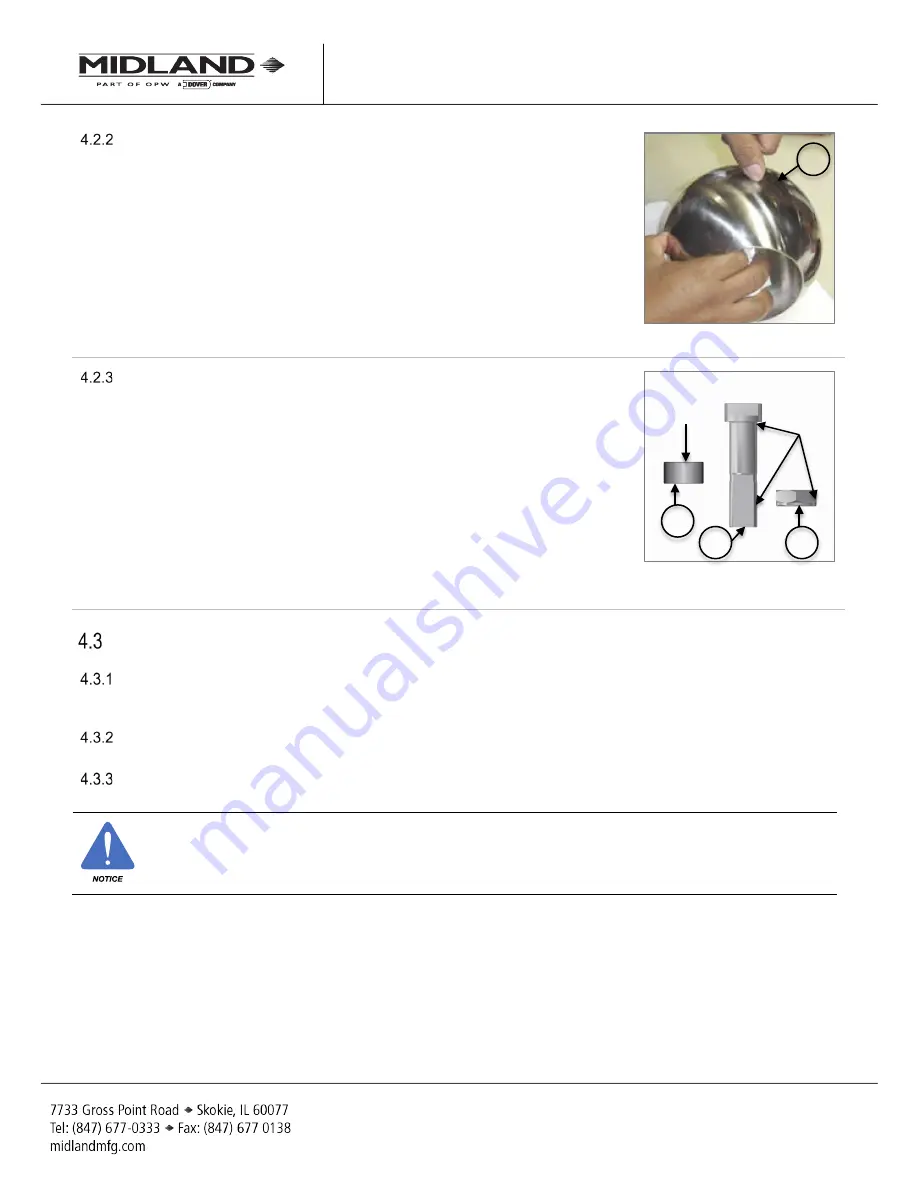
4.2.2.1  Clean the valve ball (item 3) with soap and water or in an ultrasonic bath, or 

both, to remove adhering product. 

4.2.2.2  Slide your fingernail over scratches to determine severity. If your fingernail 

is unable to “catch” in an abrasion, it is not of a depth that would allow 

leakage or affect the ball seals.  

4.2.2.3  If any of the scratches fail the fingernail test, replace the ball. It cannot be 

repaired. 

Figure 4-14 Check Scratch Severity 

Valve-Stem Components Inspection 

4.2.3.1  The  stem (item 2) 1-1/8”-12 UNF threads should pass a thread-ring Go-

Gauge test. If the threads exhibit stripping or irreparable damage, replace 

the valve stem.  

4.2.3.2  Inspect the surfaces of the spacer (item 6) bushing that contacts the stem 

packing and thrust washer as shown in Figure 4-5. Also, inspect the surface 

of the stem shaft. These surfaces should be smooth and clean. 

4.2.3.3  Inspect the valve stem locknut for damage to the threads and the Nylon

®


locking insert. Replace the locknut if damage is observed and if the Nylon

®


insers is cracked, damaged or frayed.  

Figure 4-15 Valve Stem and Spacer 

Surfaces 

Special Inspection Considerations 

Previous procedures may not cover all conditions encountered in the field. Therefore, it is the responsibility of 

the repair agency to contact an authorized Midland technical representative for recommendations regarding 

unusual valve conditions or repair circumstances that may be encountered.  
Evaluation of critical component metal surfaces of the valves after cleaning and inspection, by the repair facility 

are the respsonsibility of the repair facility. 
Where numerical tolerances cannot be provided, the disposition of the part or parts is under the jurisdiction of 

the repair facility and dependent on its experience and judgment. 

NOTICE: 

To ensure best practices and consistency of your qualification procedure, gaskets, O-rings, valve 

seats and wire seals should always be replaced.   

 3 

13 

Critical 

Surfaces 

 2 

 6 

Critical 

Surface 

A-520/A-522/A-522A

, Rev. 3.0

Содержание 510-10-04-ST

Страница 1: ...l 01 2021 Supersedes A 520 522 Rev 2 2 Manual content is subject to change Visit www midlandmfg com for latest manual revision and revision history A 520 A 522 A 522A Series 4 Bottom Outlet Ball Valve...

Страница 2: ...mponent Identification and Parts Listings 4 Steam Jacket Configurations 10 3 Valve Installation 12 Installation Procedure and Required Tools 12 Leak Inspection 14 Valve Operation Notes and Precautions...

Страница 3: ...conform to all applicable specifications from TC AAR DOT CFR Parts 173 31 174 67 etc and other governmental bodies along with the operating instructions of your company Safety Warnings and Precaution...

Страница 4: ...SS STEEL 5 1 PACKING 520 5 01 TF VIRGIN TEFLON 520 5 01 TF VIRGIN TEFLON 6 1 SPACER 520 6 SS STAINLESS STEEL 520 6 SS STAINLESS STEEL 7 1 PIN 520 7 CS STEEL 520 7 CS STEEL 8 1 STOP PLATE 520 8 CS STEE...

Страница 5: ...1 STOP PLATE 520 8 CS STEEL PLATED 520 8 CS STEEL PLATED 9 8 CAP SCREW HEX SOCKET 5 8 11 UNC 2A X 1 LG 520 9 CS STEEL 520 9 CS STEEL 10 2 SEAL BALL SEE TABLE SEE TABLE SEE TABLE SEE TABLE 11 1 SEAL V...

Страница 6: ...8 CS STEEL PLATED 520 8 CS STEEL PLATED 9 8 CAP SCREW HEX SOCKET 5 8 11 UNC 2A X 1 LG 520 9 CS STEEL 520 9 CS STEEL 10 2 SEAL BALL SEE TABLE SEE TABLE SEE TABLE SEE TABLE 11 1 SEAL VALVE BODY 520 11 0...

Страница 7: ...STEEL PLATED 9 8 CAP SCREW HEX SOCKET 5 8 11 UNC 2A X 1 LG 520 9 CS STEEL 520 9 CS STEEL 10 2 SEAL BALL SEE TABLE SEE TABLE SEE TABLE SEE TABLE 11 1 SEAL VALVE BODY 520 11 01 TF VIRGIN TEFLON 520 11...

Страница 8: ...6 SS STAINLESS STEEL 520 6 SS STAINLESS STEEL 7 1 PIN 520 7 CS STEEL 520 7 CS STEEL 8 1 STOP PLATE 520 8 CS STEEL PLATED 520 8 CS STEEL PLATED 9 8 CAP SCREW HEX SOCKET 5 8 11 UNC 2A X 1 LG 520 9 CS S...

Страница 9: ...Manual content is subject to change Visit midlandmfg com for latest IOM revision and revision history Figure 2 1 A 52X Component Identification Figure 2 2 A 522A Component Identification A 520 A 522 A...

Страница 10: ...evision history Steam Jacket Configurations Note that only the legacy A 522 models have a steam jacket configuration the updated A 522A does not have this configuration Figure 2 3 A 520 SJ Valve w Ste...

Страница 11: ...to change Visit midlandmfg com for latest IOM revision and revision history NOTICE Shown for information only For specific details on steam jackets i e part numbers and dimensions contact Midland Cust...

Страница 12: ...sure easy installation of the new mounting hardware Using a lint free cloth and appropriate cleaning solvent wipe clean the mounting and tongue Inspect the sides and edges of the tank car tongue Becau...

Страница 13: ...er when lifting and locating the valve during installation Raise the valve only until the gasket groove engages with the mounting flange tongue Install four 4 mounting bolts 90 apart and tighten them...

Страница 14: ...d gaskets may result in leaks at the valve mounting joint Inspect for leaks Follow your company s leak testing procedure Valve Operation Notes and Precautions NOTICE Valve Operation Operation and use...

Страница 15: ...ools SAE Wrench Component s Description 1 5 8 Wrench Locknut item 13 5 8 Allen Wrench Cap Screws item 9 Other Tools Supplies and Equipment Thread Go No Go Gauge Stem item 2 Figure 4 1 Required Tools f...

Страница 16: ...avoid contacting it with the valve ball item 3 Remove valve body seal item 11 from the body item 4 Remove the ball seal Item 10 from the cap item 1 4 1 6 1 If handling an A 522A remove the cap ball s...

Страница 17: ...stance of the compressed stem packing Figure 4 8 Remove Stop Plate and Stem Remove the stainless steel spacer collar Item 6 from the valve stem bore Figure 4 9 Remove Space Collar Remove the Teflon pa...

Страница 18: ...ces can be provided the disposition of the internal integrity and surface quality of parts is under the jurisdiction of the repair facility and dependent on its experience and judgment Key components...

Страница 19: ...surfaces should be smooth and clean 4 2 3 3 Inspect the valve stem locknut for damage to the threads and the Nylon locking insert Replace the locknut if damage is observed and if the Nylon insers is c...

Страница 20: ...the essential guidelines Valve Assembly and Testing Procedure SAE Wrench Component s Description Torque ft lb 1 5 8 Wrench Locknut item 13 5 8 Allen Wrench Cap Screws item 9 1 5 8 Torque Wrench Lockn...

Страница 21: ...valve stem pushing them into the shaft bore CAUTION Packing Ring Order There are three 3 types of Teflon rings that comprise the valve stem packing five 5 rings total Do not alter their arrangement o...

Страница 22: ...nt hole that would negatively impact orientation Alt Using an assembly tool that is compatible with the threaded end of the stem or temporary handle installation turn the stem to put the valve in the...

Страница 23: ...l item 3 with warm water and soap or immerse it in a heated ultrasonic bath 125 F 150 F for five 5 minutes Then rinse the ball with clean cold water Dry it with a lint free coth NOTICE Allow the valve...

Страница 24: ...Ball Seal Wipe down the large Teflon valve body seal item 11 and install onto the body item 4 Place the cap plate item 1 with seal item 10 onto the valve body item 4 Figure 4 28 Install Seal on Cap Or...

Страница 25: ...auge to confirm that the cap is in contact with the valve body item 4 all around with no gaps allowed NOTICE Cap Bolt Torqe If uniform cap to body contact is not achieved increase the torque on the ca...

Страница 26: ...eg closure During this period apply leak detecting fluid snoop to the exterior of the spacer protruding from the shaft bore while watching for any bubbles and foaming No leaks are allowed After first...

Страница 27: ...ing the valve for leaks If the valve is leaking from its outlet port rebuild or replace it If minor leakage is detected only at the valve stem packing remove the handle and increase the tightening tor...

Страница 28: ...Copyright 2021 OPW Printed in USA 2021 Delaware Capital Formation Inc All Rights Reserved...

Отзывы: