5
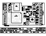
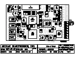
P2 – Non-Connector Side
P2-1
– Keypad Column 3 Input
P2-2
– Keypad Column 2 Input. Can also be used with a binary switch to select security codes.
P2-3
– Keypad Column 1 Input
P2-4
– Keypad Row 4 Input
P2-5
– Keypad Row 3 Input
P2-6
– Keypad Row 2 Input. Can also be used with a binary switch to select security codes.
P2-7
– Keypad Row 1 Input
P2-8
– Program Input – Connect this lead to the green clip lead from the KL-3 programmer.
P2-9
– Squelch/Disable Output – When used as Squelch Output, this lead can be used to mute the radio’s audio
power amplifier by the scrambler. Using this lead to mute the radio is optional since the scrambler can mute
internally. When programmed as Disable Output, this output will be active when the disable command is
transmitted from the CAD-300/DDU-300 and will remain active until re-enabled from the CAD-300/DDU-300.
P2-10
– Program Output – Connect this lead to the yellow clip lead from the KL-3 programmer.
P2-11
– Trunking Delay Input – This input should be used in trunked radios with a channel acquisition strobe
output. When used, the scrambler will wait up to 5 seconds for a channel to be acquired. After 5 seconds the
PTT must be reset. If this input is not used, program the trunk delay polarity to positive and leave unconnected.
P2-12
– Keypad Ground
P2-13
– Alert Tone Output - This lead outputs beep tones whenever applicable, such as when the scrambler rings
or the mode is changed. This lead should be used when the Audio Enable Output is insufficient for turning on the
radio’s audio amplifier. This lead should be connected directly to the high side of the radio’s speaker. If neither
side of the speaker is connected to ground, the Audio Enable Output may be used to supply a ground to the
speaker when tones are being output. Be sure this will not damage the radio’s audio amplifier or Q2.

