Midea MFA-12HRN1 Скачать руководство пользователя страница 1

MCAC-UTSM-2009-03 

Contents 

Contents 


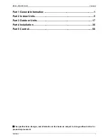
Part 1 General Information ........................................................................ 1


Part 2 Indoor Units ...................................................................................... 5


Part 3 Outdoor Units ................................................................................. 17


Part 4 Installation ...................................................................................... 36


Part 5 Control ............................................................................................ 56


The specifications, designs, and information in this book are subject to change without notice for 

product improvement. 

Содержание MFA-12HRN1

Страница 1: ...i Part 1 General Information 1 Part 2 Indoor Units 5 Part 3 Outdoor Units 17 Part 4 Installation 36 Part 5 Control 56 The specifications designs and information in this book are subject to change wit...

Страница 2: ......

Страница 3: ...2009 03 General Information General Information 1 Part 1 General Information 1 Model Names of Indoor Outdoor Units 2 2 External Appearance 2 2 1 Indoor Units 2 2 2 Outdoor Units 2 3 Nomenclature 3 4 F...

Страница 4: ...pth 210 15 20 220 240V 1ph 50Hz MFA 12HRN1 Q Width 700 Height 600 Depth 210 20 25 220 240V 1ph 50Hz 1 2 Outdoor Units Model name Dimension mm Net Gross weight kg Power supply MON 12HN1 Width 780 Heigh...

Страница 5: ...de R Remote Control Function Code C Cooling Only H Cooling Heating Capacity 1000Btu h Product Series A 1st Designed Product Category F Console Type Midea 3 2 Outdoor Unit M O N 12 H N1 Q Q Quickly Cou...

Страница 6: ...le installation can be used for floor standing or lower wall applications 4 High efficiency filter built in Formaldehyde nemesis filter active carbon and biological anti virus filter is optional 5 Com...

Страница 7: ...Part 2 Indoor Units 1 Specifications 6 2 Dimensions 7 3 Service Space 7 4 Wiring Diagrams 8 5 Air Velocity and Temperature Distributions 9 6 Capacity Tables 10 7 Electric Characteristics 13 8 Sound L...

Страница 8: ...hilic aluminum Hydrophilic aluminum Tube outside dia and type mm 7 Inner grooved copper tube 7 Inner grooved copper tube 7 Inner grooved copper tube Coil length height width mm 512 378 26 74 512 378 2...

Страница 9: ...MCAC UTSM 2009 03 Dimensions Indoor Units 7 2 Dimensions 3 Service Space...

Страница 10: ...Wiring Diagrams MCAC UTSM 2009 03 8 Indoor Units 4 Wiring Diagrams 4 1 MFA 12HRN1 MFA 18HRN1 4 2 MFA 12HRN1 Q...

Страница 11: ...MCAC UTSM 2009 03 Air Velocity and Temperature Distributions Indoor Units 9 5 Air Velocity and Temperature Distributions Discharge angle 60 Airflow velocity Temperature...

Страница 12: ...54 2 52 2 49 2 42 Input 0 96 1 03 1 07 1 13 27 19 C DB WB TC 3 46 3 30 3 22 2 98 SC 2 56 2 54 2 50 2 44 Input 0 99 1 04 1 096 1 15 32 23 C DB WB TC 3 52 3 39 3 33 3 07 SC 2 99 2 95 2 93 2 86 Input 1...

Страница 13: ...4 12 4 01 Input 1 40 1 50 1 56 1 64 27 19 C DB WB TC 5 72 5 46 5 30 4 93 SC 4 24 4 20 4 13 4 04 Input 1 43 1 51 1 65 1 67 32 23 C DB WB TC 5 83 5 62 5 51 5 09 SC 4 96 4 89 4 85 4 73 Input 1 50 1 56 1...

Страница 14: ...19 C DB WB TC 3 46 3 30 3 21 2 98 SC 2 56 2 54 2 50 2 44 Input 0 99 1 05 1 101 1 16 32 23 C DB WB TC 3 52 3 39 3 33 3 07 SC 2 99 2 95 2 93 2 86 Input 1 03 1 08 1 16 1 20 Heating capacity Heating Outd...

Страница 15: ...Max MCA MFA kW FLA MFA 12HRN1 Q 50 220 240V 198V 254V 0 1 15 0 02 0 08 MFA 18HRN1 50 220 240V 198V 254V 0 156 20 0 02 0 125 Remark MCA Min Current Amps A MFA Max Fuse Amps A KW Fan Motor Rated Output...

Страница 16: ...rmaldehyde killer 2 14 5 Room temp sensor ass y 1 6 Air guide ring ass y 1 15 Wire clamp 1 7 Panel ass y 1 16 Motor bracket 1 8 Centrifugal fan 1 17 Dc motor 1 9 Air outlet frame ass y 1 18 Evaporator...

Страница 17: ...Air guide ring ass y 1 16 Motor bracket 1 7 Panel ass y 1 17 Dc motor 1 8 Centrifugal fan 1 18 Evaporator ass y 1 9 Air outlet frame ass y 1 18 1 Output pipe ass y 1 9 1 Stepper motor 1 18 2 Input pip...

Страница 18: ...troller 1 Frame 1 Mounting screw ST2 9 10 C H 2 Alkaline dry batteries AM4 2 Others Installation manual 1 Owner s manual 1 10 2 MFA 12HRN1 Q Name Shape Quantity Installation fittings Hook 2 Remote con...

Страница 19: ...Units 17 Part 3 Outdoor Units 1 Specifications 18 2 Dimensions 19 3 Service Space 20 4 Piping Diagrams 20 5 Wiring Diagrams 21 6 Electric Characteristics 24 7 Operation Limits 24 8 Sound Levels 25 9...

Страница 20: ...nd WELLING WELLING WELLING Input W 58 130 58 Capacitor F 2 5 F 450V 2 5 F 450V 2 5 F 450V Speed r min 800 750 800 Outdoor coil Number of rows 2 2 2 Tube pitch a row pitch b mm 21 13 37 22 19 05 21 13...

Страница 21: ...MCAC UTSM 2009 03 Dimensions Outdoor Units 19 2 Dimensions 2 1 MON 12HN1 MON 12HN1 Q 2 2 MON 18HN1...

Страница 22: ...20 Outdoor Units 3 Service Space 4 Piping Diagrams T1 T2 Indoor units Outdoor unit stop valve room temp sensor evaporator temp sensor 4 way valve compressor condenser temp sensor stop valve one way va...

Страница 23: ...MCAC UTSM 2009 03 Wiring Diagrams Outdoor Units 21 5 Wiring Diagrams 5 1 MON 12HN1...

Страница 24: ...Wiring Diagrams MCAC UTSM 2009 03 22 Outdoor Units 5 2 MON 18HN1...

Страница 25: ...MCAC UTSM 2009 03 Wiring Diagrams Outdoor Units 23 5 3 MON 12HN1 Q...

Страница 26: ...13 15 29 9 5 3 0 024 0 275 Remark MCA Min Current Amps A TOCA Total Over current Amps A MFA Max Fuse Amps A MSC Max Starting Amps A RLA Rated Locked Amps A OFM Outdoor Fan Motor FLA Full Load Amps A...

Страница 27: ...MCAC UTSM 2009 03 Sound Levels Outdoor Units 25 8 Sound Levels Microphone Outdoor Unit H 1 0m Note H 0 5 height of outdoor unit Model Noise level dB A MON 12HN1 52 8 MON 18HN1 55 5 MON 12HN1 Q 52 6...

Страница 28: ...s y 1 12 Front panel 1 4 4 Condenser inlet pipe ass y 1 13 Compressor 1 5 E part box ass y 1 14 Net clamp 6 5 1 Wire joint 4p 1 15 Right clapboard 1 5 2 Transformer 1 16 Partition board ass y 1 5 3 Co...

Страница 29: ...oard ass y 1 9 Drainage cover 1 20 6 Transformer 1 10 Valve plate 1 20 7 Relay 1 11 Base ass y 1 21 Drain hose 1 12 High pressure valve ass y 1 22 Net clamp 8 12 1 Strainer 1 23 Temp sensor ass y 1 12...

Страница 30: ...nnecting pipe ass y 1 11 Base ass y 1 4 4 Condenser inlet pipe ass y 1 12 Grille 1 5 E part box ass y 1 13 Front panel 1 5 1 Connect wiring 1 14 Compressor 1 5 2 Transformer 1 15 Net clamp 6 5 3 Compr...

Страница 31: ...ing channel is abnormal 3 Condenser temp sensor checking channel is abnormal 4 In outdoor unit communication malfunction 5 DC Fan malfunction 6 EEPROM malfunction Extinguish Flash at 5Hz Light 1 Runni...

Страница 32: ...e of the evaporator temp sensor is correct according to Annex 1 Yes Replace the evaporator temp sensor Replace the indoor main board No Judge Condenser temp sensor checking channel is abnormal Validat...

Страница 33: ...In outdoor unit communication malfunction Judge 1 Check whether the wiring of communication line is break off Yes Connect the wiring well Judge 2 Check whether the wiring of L N and S is wrong No Conn...

Страница 34: ...off Yes Connect the wiring well No Judge 2 Check whether the DC fan is failure Running lamp and Defrosting lamp flash at 5Hz the Timer lamp light EEPROM malfunction Judge 1 Check whether the EEPROM is...

Страница 35: ...3 condenser pipe temp sensor malfunction Extinguish Flash 1 LED1 and LED3 flash LED1 and LED3 flash In outdoor unit communication malfunction Judge 1 Check whether the wiring of communication line is...

Страница 36: ...flash T3 condenser pipe temp sensor malfunction Check whether the temp sensor is connected well No Connect it well LED2 and LED3 flash Check whether the resistance of the temp sensor is correct accor...

Страница 37: ...0000 36 6 13059 76 1 34105 116 0 40060 3 41 5878 37 5 87359 77 1 29078 117 0 38991 2 39 8239 38 5 62961 78 1 25423 118 0 37956 1 37 1988 39 5 39689 79 1 21330 119 0 36954 0 35 2024 40 5 17519 80 1 17...

Страница 38: ...3 36 Installation Part 4 Installation 1 Installation Place 37 2 Installation of Indoor Unit 38 3 Installation of outdoor unit 40 4 Installation of the Connecting Pipe 41 5 Connect the Drain Pipe 48 6...

Страница 39: ...od will not feel uncomfortable with the noise or expelled air 6 There is no leakage of combustible gas 7 It is easy to install the connecting pipe or cables Caution Don t install the air conditioner i...

Страница 40: ...nd the influence of external air is the least The air flow can reach throughout the room The connecting pipe and drainpipe could be extracted out easily There is no direct radiation from heaters Cauti...

Страница 41: ...Indoor Unit Installation 39 2 2 Installation the main body z Fix the hook with tapping screw onto the wall z Hang the indoor unit on the hook The bottom of body can touch with floor or suspended but...

Страница 42: ...ble to the situation of an airtight room Leave open two of the three directions M N P 3 2 Moving and Installing 1 Since the gravity center of the unit is not at its physical center so please be carefu...

Страница 43: ...ing Pipe Installation 41 4 Installation of the Connecting Pipe Caution For your safety always wear safety eye wear and work gloves when connecting the pipes 4 1 MFA 12HRN1 Q Quick connecter Remove the...

Страница 44: ...ated on the indoor unit into the female coupling Step 3 Release the Release Sleeve to the lock the male coupling into places Step 4 Fold the male coupling handle towards the female coupling half and p...

Страница 45: ...iping and the liquid piping Otherwise this can sometimes result in water leakage 1 Drill a hole in the wall suitable just for the size of the wall conduit then set on the fittings such as the wall con...

Страница 46: ...llation How to take indoor unit apart to connect the pipes 1 Open the front panel Slide the two stoppers on the left and right sides until they click 2 Remove the front panel Remove the string Allowin...

Страница 47: ...the face plate Remove the four screws Opening bottom of face plate for a angle that is 30 degree then the top of face plate will be take up How to take outdoor unit apart to connect the pipes Remove t...

Страница 48: ...it z Bend the tubing in proper way Do not harm to them z The bending angle should not exceed 90 z Bending position is preferably in the middle of the bendable pipe The larger the bending radius the be...

Страница 49: ...gonal wrench 10 mm 36 44 25 4 Caution z Always use a charge hose for service port connection z After tightening the cap check that no refrigerant leaks are present Using the vacuum pump 1 Loosen and r...

Страница 50: ...mm L m 6 4 9 5 Less than 5m One way Added refrigerant when over 5m One way 11g m L 5 30g m L 5 R g Additional refrigerant to be charged L m The length of the refrigerant pipe one way D mm Liquid side...

Страница 51: ...ving the ceiling 5 3 Install the drain joint of the outdoor unit Fit the seal into the drain elbow then insert the drain elbow into the base pan hole of outdoor unit rotate 90 to securely assemble the...

Страница 52: ...n the control board 2 Remove the control cover from the outdoor unit by loosening the screw 3 Hold the indoor plug connector and insert the mating plug connector located on the outdoor unit until it f...

Страница 53: ...sure to locate the power wiring and the signal wring well to avoid cross disturbance 7 Do not turn on the power until you have checked carefully after wiring Remark per EMC Directive 89 336 EEC For to...

Страница 54: ...entified with their respective matched numbers on the terminal block of indoor and outdoor units 4 Re install the indoor unit and outdoor unit 6 2 2 The Specification of Power Type 12000Btu h 18000Btu...

Страница 55: ...MCAC UTSM 2009 03 Wiring Installation 53 6 2 3 Wiring figure...

Страница 56: ...SM 2009 03 54 Installation Note All the pictures in this manual are for explanation purpose only They may be slightly different from the air conditioner you purchased depend on model The actual shape...

Страница 57: ...an reach the indoor unit smoothly 4 Test operation Set the air conditioner under the mode of COOLING with the remote controller and check the following points If there is any malfunction please resolv...

Страница 58: ...Control MCAC UTSM 2009 03 56 Control Part 5 Control 1 Wireless remote controller R51D E 57...

Страница 59: ...nit operation Push the button again to stop the unit operation 4 MODE Select Button Each time you push the button a mode is selected in a sequence that goes from AUTO COOL DRY HEAT and FAN as the foll...

Страница 60: ...g under the powerful cooling mode 1 3 Names and Functions of indicators on Remote Controller 1 2 4 6 7 5 4 3 Display Panel TIMER ON OFF 1 DIGITAL DISPLAY area This area will show the temperature and i...

Отзывы: