background image

INSTALLATION AND OPERATION MANUAL, GAS KETTLES, MODELS GL-40FE, GL-60FE

2.0  INSTALLATION 

(Continued)

TO INSTALL

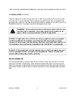
1. Uncrate carefully.  Report any hidden freight damage to the freight company immediately.

2. Set the unit in place.  Be certain to maintain minimum clearances as stated above.  

3. To level the unit use a spirit level in all directions on the top of the kettle (lid up).

1. Units with legs - adjust the bottom foot on each leg to overcome an uneven floor.

2. Units with casters - loosen the locking nuts, turn casters in or out as required and

tighten locking  nuts.

4. Be certain to leave adequate clearances for cleaning, maintenance and service.

5. The pressure relief valve is located at the left rear of the unit.  This area should be kept

clear and should not be in an area where operators will normally stand.  The elbow on the
relief valve should be turned toward the floor.  A maximum 3 foot, 3/4" diameter pipe may
be used to extend to the floor, but must not be piped directly to a drain.  It must vent to the
atmosphere.

6. Check the pressure gauge on the front panel before operating.  If the pressure gauge does

not indicate green vacuum zone (below 0 psi), see “Re-establishing Vacuum” section under
SERVICE, after completing installation instructions.

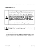
GAS CONNECTION

The serial plate on the lower right side of the unit indicates the type of gas your unit is equipped
to burn.  Do 

NOT

 connect to any other gas type.

A 1" NPT line is provided at the rear for the connection.  Each unit is equipped with an internal
pressure regulator which is set for 4" W.C. manifold pressure for natural gas and 10" W.C.


for

propane gas.  Use 1/8" pipe tap on the burner manifold for checking pressure.

An adequate gas supply is imperative.  Undersized or low pressure lines will restrict the volume
of gas required for satisfactory performance.  A steady pressure, minimum 6" W.C. for natural
gas and minimum 11" W.C. for propane gas, is recommended.  With all units operating
simultaneously, the manifold pressure on all units should not show any appreciable drop. 
Fluctuations of more than 25% on natural gas, and 10% on propane gas, will create pilot
problems and affect burner operating characteristics.  Contact your gas company for correct
supply line sizes.  

Part No. 10199R1

7

2016-12-19

Содержание CROWN GL-40FE

Страница 1: ...nance instructions thoroughly before installing or servicing this equipment IMPORTANT FOR FUTURE REFERENCE Please complete this information and retain this manual for the life of the equipment Model _...

Страница 2: ...or death Read the installation operating and maintenance instructions thoroughly before installing operating or servicing this equipment PURCHASER Instructions to be followed in the event that the ope...

Страница 3: ...RIPTION PAGE Important Notes for Installation and Operation 2 1 0 Service Connections 4 2 0 Installation 5 3 0 Performance Check 11 4 0 Operation 12 5 0 Cleaning 18 6 0 Maintenance 23 7 0 Service 25 8...

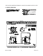
Страница 4: ...INSTALLATION AND OPERATION MANUAL GAS KETTLES MODELS GL 40FE GL 60FE 1 0 SERVICE CONNECTIONS Part No 10199R1 4 2016 12 19...

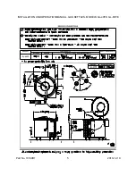
Страница 5: ...INSTALLATION AND OPERATION MANUAL GAS KETTLES MODELS GL 40FE GL 60FE Part No 10199R1 5 2016 12 19...

Страница 6: ...d that a canopy extend 6 past appliance and be located 7 5 feet from the floor Filters should be installed at an angle of 45 degrees or more with the horizontal This position prevents dripping of grea...

Страница 7: ...the pressure gauge on the front panel before operating If the pressure gauge does not indicate green vacuum zone below 0 psi see Re establishing Vacuum section under SERVICE after completing installa...

Страница 8: ...gas appliance pressure regulator shall be installed to the outdoors in accordance with local codes or in the absence of local codes with the National Fuel Gas Code ANSI Z223 1 NFPA 54 or the Natural...

Страница 9: ...uick disconnect device or its associated piping to limit the appliance movement the location where the restraining means may be attached to the appliance is on bottom of unit directly below relief val...

Страница 10: ...is electrical rating are factory equipped with a transformer To connect supply wires remove cover from transformer box at right rear of unit Route supply wires and ground wire through the hole in the...

Страница 11: ...erify correct gas type 2 Verify correct voltage cycle and phase 3 Gas pressure 4 Internal gas connections 5 Internal electrical connections 6 Pilots adjustment and ignition 7 Burners adjustment and ig...

Страница 12: ...A START UP 1 Turn thermostat to OFF position and power switch to OFF position 2 Open control panel access door located on right side at bottom 3 Turn dial on combination control to ON position by rot...

Страница 13: ...out period until the air is purged from the gas line B SHUTDOWN 1 STANDBY 1 Place power on switch and thermostat to OFF position 2 COMPLETE 1 Place power on switch and thermostat to OFF position 2 Tur...

Страница 14: ...on if not already on 5 Turn power switch to ON position 6 Wait two minutes and ten seconds and then immediately light pilot with long match or taper 7 After 10 15 seconds gas valve will allow main bur...

Страница 15: ...e Adding Water section of service instructions 4 Thermostat The thermostat selects the desired internal kettle operating temperature 5 Pressure Gauge The pressure gauge indicates the internal operatin...

Страница 16: ...it when the appliance is moved to its originally installed position Turning on the power switch initiates a pilot lighting sequence The spark igniter will begin sparking The spark igniter will spark u...

Страница 17: ...f the liquid and stir to form a thin paste Turn on the kettle and add the remainder of the liquid Continue as per recipe instructions When browning meat bring the kettle up to temperature before addin...

Страница 18: ...e a mild detergent warm water and rinse thoroughly Never spray water into electric controls NOTICE Draw off valve has a vulcanized rubber coated stem for better sealing Do not over tighten This may ca...

Страница 19: ...rgent and water solution to drain 4 Wipe the exterior of the kettle with a clean damp cloth WARNING If you are cleaning a valve that is assembled to a kettle be sure the kettle is completely empty of...

Страница 20: ...rectly and could leak 3 Use a soft cloth or soft brush and clean all surfaces 4 Using both hands remove the valve from the soap and rinse well in another plastic pail that contains fresh water 5 Wash...

Страница 21: ...e vinegar away with fresh clear water Dry the surface completely and allow one hour before using the appliance to cook Following daily and period maintenance procedures will prolong the life for your...

Страница 22: ...Darkened areas sometimes appear on stainless steel surfaces where the area has been subjected to excessive heat These darkened areas are caused by thickening of the protective surface of the stainles...

Страница 23: ...enance and repairs WARNING Disconnect the power supply to the appliance before cleaning or servicing Daily 1 Wash exposed cleanable areas Monthly 1 Clean around burner air mixers louvered panels and p...

Страница 24: ...pressure fluid may be discharged from body drain and vent during try lever test Care must be taken to avoid any bodily contact CAUTION High sound levels may be experienced during try lever test Wear...

Страница 25: ...red Wiring diagrams for the unit are located in a small envelope affixed to the rear side of the front control panel Orifice Size Unit Total Input Natural Propane GL 40F 130 000 BTU Hour 23 39 MANIFOL...

Страница 26: ...efer to Figure 1 2 Turn the inner adjustment screw clockwise to decrease or counterclockwise to increase the pilot flame 3 Always replace the cover screw after adjustment and tighten firmly to ensure...

Страница 27: ...following before changing the thermostat 1 With kettle cool the pressure reading on the pressure gauge should be in the green vacuum zone below 0 psi If not see Re establishing Vacuum section 2 Check...

Страница 28: ...el must be removed Remove the screws on either side of the panel Be sure to support the panel to avoid excessive strain on the wiring 2 To increase the pressure setting turn the white ribbed knob cloc...

Страница 29: ...een added replace and tighten the nut 6 Vacuum must be re established See Re establishing Vacuum For reference the total amount of distilled water contained in each unit and amount to be added in a lo...

Страница 30: ...l to the kettle CONVERTING BETWEEN NATURAL AND PROPANE GAS WARNING Fire or explosion hazard can cause property damage severe injury or death 1 Do not attempt to use a gas control set for natural gas o...

Страница 31: ...gulator Turn the pressure regulator adjustment screw clockwise six complete turns This provides a preliminary pressure setting of about 10 0 inch W C 2 5 kPa for LP regulator and 3 5 inch W C 0 9 kPa...

Страница 32: ...ION AND OPERATION MANUAL GAS KETTLES MODELS GL 40FE GL 60FE Figure 1 Top view of gas control Figure 2 Installation of conversion kit in regulated gas control 7 0 SERVICE Continued Part No 10199R1 32 2...

Страница 33: ...odule Bad low water control Bad spark igniter Bad intermittent pilot burner Fuse in unit blown Unit will turn on electrically but will not heat Lockout has occurred Thermostat not on Gas control valve...

Страница 34: ...gas control Unit slow to preheat and slow to recover Propane gas on natural Low gas pressure Incorrect orifice sizes Loss of vacuum Faulty regulator in gas control Unit continuously locks out Pilot ga...

Страница 35: ...98 8282 Sarnia Ontario 519 339 3711 Varennes Quebec 450 652 1000 Product DOWFROST HD HEAT TRANSFER FLUID DYED Product Code 04632 Effective Date 2 20 01 Date Printed 07 10 02 MSD 002239 DOW CHEMICAL CA...

Страница 36: ...ity is considered to be extremely low No hazards anticipated from swallowing small amounts incidental to normal handling operations INHALATION At room temperature vapours are minimal due to physical p...

Страница 37: ...dote Supportive care Treatment based on judgment of the physician in response to reactions of the patient 5 FIRE FIGHTING MEASURES FLAMMABLE PROPERTIES FLASH POINT 214EF 107EC based on a similar mater...

Страница 38: ...ater to protect personnel and minimize property damage Burning liquids may be extinguished by dilution with water Do not use direct water stream May spread fire Fight fire from protected location or s...

Страница 39: ...glasses should be sufficient for most operations however for misty operations wear chemical goggles SKIN PROTECTION Use gloves impervious to this material RESPIRATORY PROTECTION Atmospheric levels sho...

Страница 40: ...cur 11 TOXICOLOGICAL INFORMATION See Section 3 for Potential Health Effects For detailed toxicological data write or call the address or non emergency number shown in Section 1 SKIN The LD50 for skin...

Страница 41: ...MPANY HAS NO CONTROL OVER THE MANAGEMENT PRACTICES OR MANUFACTURING PROCESSES OF PARTIES HANDLING OR USING THIS MATERIAL THE INFORMATION PRESENTED HERE PERTAINS ONLY TO THE PRODUCT AS SHIPPED IN ITS I...

Страница 42: ...hown above However no warranty express or implied is given Regulatory requirements are subject to change and may differ from one location to another it is the buyer s responsibility to ensure that its...

Страница 43: ...ble definitions to meet the following categories Not to have met any hazard category TOXIC SUBSTANCES CONTROL ACT TSCA All ingredients are on the TSCA inventory or are not required to be listed on the...

Страница 44: ...ed Product under WHMIS CANADIAN ENVIRONMENTAL PROTECTION ACT CEPA This product contains one or more substances which are not listed on the Canadian Domestic Substances List DSL Contact your Dow repres...

Отзывы: