Chapter 7 Installation
7.4.1.1 Connection examples
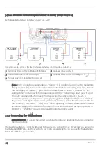
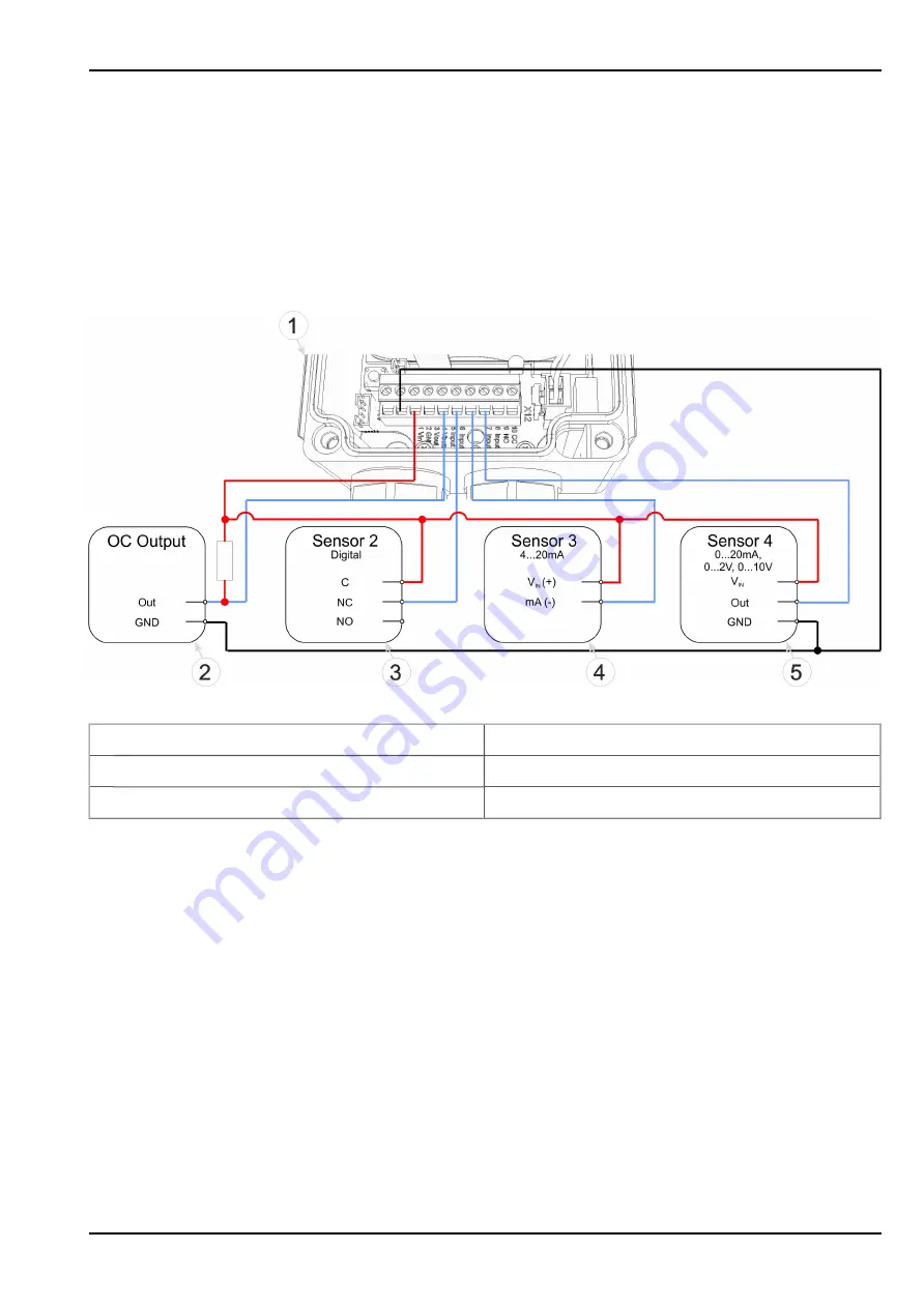
7.4.1.1.1 Use of the switchable sensor supply K3
Sensor supply K3: standard: 15...19,5VDC, optional: 24...31VDC
Important note: If a universal input is in "LP digital" mode, a switch contact must only be
supplied by V
batt
. Attaching an external voltage will cause damage to the universal input.
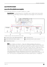
Connection examples: Use of the switchable sensor supply
1 Terminal strips of the myDatalogEASYplus
4 2-wire mA sensor
2 Sensor with open collector output
5 3-wire mA sensor or 3-wire U-sensor
3 Isolated relay contact
Note: The "Cnt.Day", "Cnt.Intervl.", "Freq" and "PWM" operating modes require a
permanent supply of the sensors. Inputs that are operated in "Digital" mode and that are to
be used to initiate a trigger event also require a permanent supply of the sensors. This can
be achieved by setting the ext. warmup time in the "Output channels" configuration section
(see "Output channels" on page 88) to a higher value than the measurement cycle (see
"Basic settings" on page 96). However, this greatly increases the energy requirements and
thus significantly shortens the operating time of the device. The use of the direct
rechargeable battery or battery voltage output (K4) is more suitable for this operation mode
(see "Use of the direct rechargeable battery or battery voltage output K4" on page 54).
Rev. 06
53
Содержание myDatalogEASYplus
Страница 2: ......
Страница 8: ...Chapter 18 Contact information 139 8 Rev 06 ...
Страница 9: ...Chapter 2 Declaration of conformity Chapter 2 Declaration of conformity Rev 06 9 ...
Страница 10: ......
Страница 22: ......
Страница 40: ......
Страница 62: ......
Страница 101: ...Chapter 9 User interfaces 9 2 2 4 GPRS SIM tariff Selected SIM tariff Rev 06 101 ...
Страница 102: ......
Страница 110: ......
Страница 112: ......
Страница 118: ......
Страница 120: ......
Страница 136: ......
Страница 138: ......

