Chapter 5 Functional principle
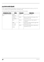
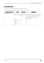
5.1.1 Filter module
The filter module is designed to compensate for brief fluctuations to the input signal. This module is
only available for the 4 universal inputs.
The following table specifies the relevant parameters for the module:
Configuration section
Mode
Parameter
Explanation
Measurement channels -
>Config.
digital
Filter time
Time in [ms] during which the signal
must remain constant to initiate a level
change. Used to suppress brief faults
(debouncing).
digital LP
Cnt.Day
Cnt.Intervl.
Freq
PWM
4-20mA
Filter time
Time in [ms] during which the analogue
signal is averaged for signal smoothing.
Used to suppress signal noise (also see
"Output channels" on page 88).
0-20mA
0-2V
0-10V
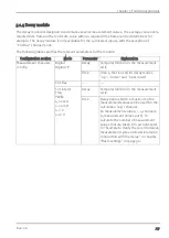
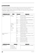
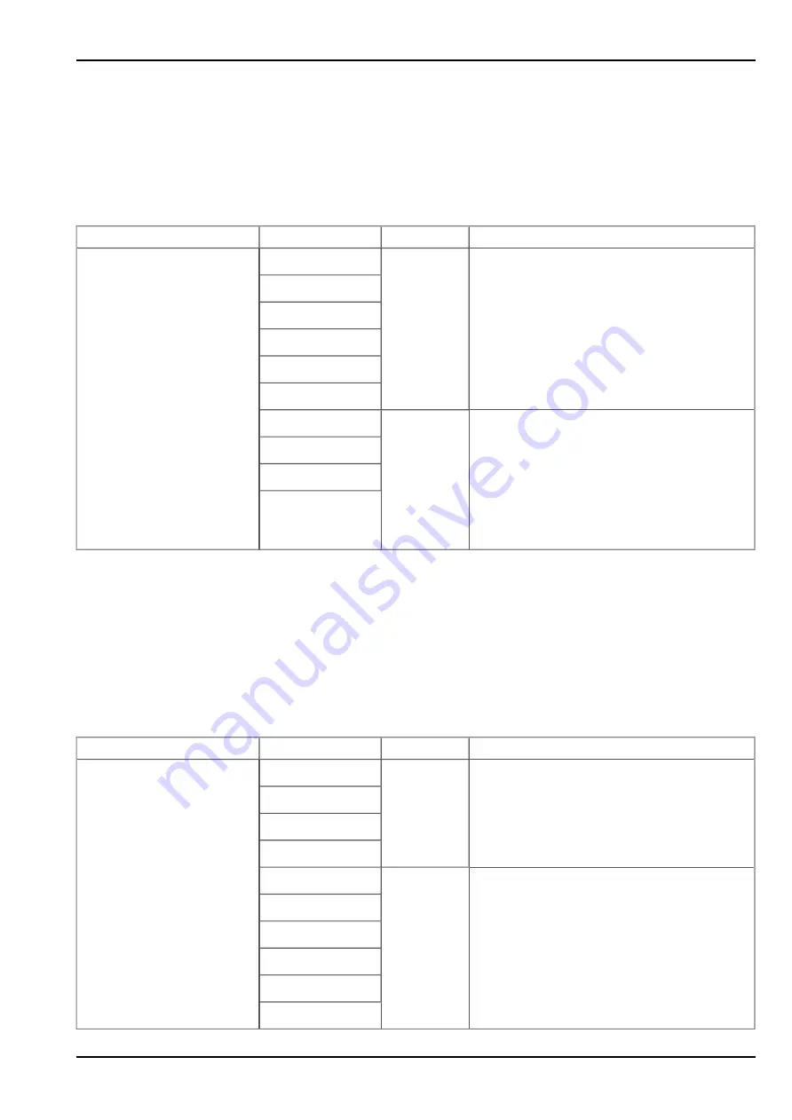
5.1.2 Overflow module
This module monitors the measurement range limits of the raw value. If a universal input was, for
example, switched to "4-20 mA" mode, a raw value of 2 mA will violate the measurement range.
The overflow module is only available for the 4 universal inputs in "Freq", "PWM", "4-20mA", "0-
20mA", "0-2V" and "0-10V" channel modes.
The following table specifies the relevant parameters for the module:
Configuration section
Modus/interface Parameter
Explanation
Measurement channels -
>Config.
digital
---
---
digital LP
Cnt.Day
Cnt.Intervl.
Freq
Out of
range
Procedure in the event of measurement
range violations
PWM
4-20mA
0-20mA
0-2V
0-10V
Rev. 06
27
Содержание myDatalogEASYplus
Страница 2: ......
Страница 8: ...Chapter 18 Contact information 139 8 Rev 06 ...
Страница 9: ...Chapter 2 Declaration of conformity Chapter 2 Declaration of conformity Rev 06 9 ...
Страница 10: ......
Страница 22: ......
Страница 40: ......
Страница 62: ......
Страница 101: ...Chapter 9 User interfaces 9 2 2 4 GPRS SIM tariff Selected SIM tariff Rev 06 101 ...
Страница 102: ......
Страница 110: ......
Страница 112: ......
Страница 118: ......
Страница 120: ......
Страница 136: ......
Страница 138: ......

