


11
|
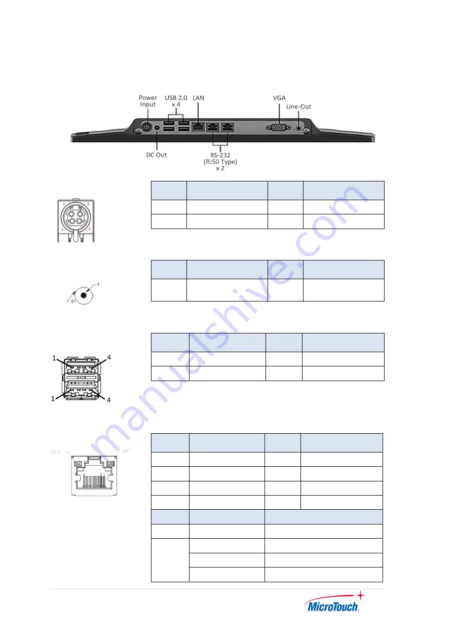
1.5 Interface Connectors
12V DC In
Pin # Signal Name
Pin # Signal Name
1
12V
2
12V
3
GND
4
GND
12V DC Out
Pin # Signal Name
Pin # Signal Name
1
12V
2
GND
USB2.0
Pin #
Signal Name
Pin #
Signal Name
1
USB5V
2
D-
3
D+
4
GND
RJ45 for LAN
Pin #
Signal Name
Pin #
Signal Name
1
TP1+
2
TP1-
3
TP2+
4
TP3-
5
TP3+
6
TP2-
7
TP4+
8
TP4-
LED
Function
Color
Left
Active
Yellow (Blink)
Right
1000M
Orange
100M
Green
10M
Non
Содержание IC-215P-AW1
Страница 1: ...11 IC 215P AW1 Touch Computer User Guide Version 1 2 2022 02 ...
Страница 8: ...7 Chapter 1 Product Introduction ...
Страница 11: ...10 1 4 Block Diagram ...
Страница 15: ...14 Chapter 2 Product Installation ...
Страница 19: ...18 2 3 Dimension 2 3 1 System Only Front View Side View Rear View Bottom View ...
Страница 20: ...19 2 3 2 System with Stand Module Front View Side View Rear View ...
Страница 27: ...26 Step 2 Remove the MSR module cable from the touch computer Step 3 To assemble the side cover Step 3 Step 2 ...
Страница 28: ...27 Chapter 3 AMI BIOS Setup ...
Страница 35: ...34 Appendix ...


