SA.45s Chip-Scale Atomic Clock
SA.45s CSAC User Guide Revision D
7
1.
2.
R. Lutwak, et. al., The Chip-Scale Atomic Clock - Low-Power Physics Package, Proceedings of the 36th
Annual Precise Time and Time Interval (PTTI) Systems and Applications Meeting, December 7–9,
2004, Washington, DC.
R. Lutwak, et. al., The MAC - A Miniature Atomic Clock, Proceedings of the 2005 Joint IEEE
International Frequency Control Symposium and Precise Time & Time Interval Systems &
Applications Meeting, August 29–31, 2005, Vancouver, BC.
3.3.2
Start-Up Sequence
Caution: To avoid severe damage to the unit, do not apply power to the incorrect terminals. The SA.45s
does not have reverse voltage protection.
When power is connected to pin 7, the SA.45s unit begins its warm-up cycle. A signal appears at the
output once power is applied to the unit. This output signal is not stable until the oscillator is locked
(indicated by the BITE pin at CMOS_low).
After 3 minutes, the CSAC achieves Lock and BITE = 0 (
"Built-In Test Equipment (BITE)" (see page 7)
Power consumption during warm-up is greater than during normal operation; it is specified on the
.
It is recommended to always allow CSAC to remain powered on for >102 seconds after it acquires LOCK.
102 seconds is the minimum amount of time necessary to save CSAC set points to memory. Otherwise,
upon the next power up, the unit may go in to a mode of operation where it re-acquires all of its set
points; warm-up time will then be out of specification.
3.3.3
Built-In Test Equipment (BITE)
CSAC state-of-health can be monitored electronically on pin 4 (BITE) of the SA.45s CSAC. Frequency lock
is indicated both by status = 0 in the status field of telemetry and by the electrical state of the BITE
output pin, which is high (logic 1) upon initial power-on and whenever status ≠ 0. The BITE pin is a high-
impedance CMOS logic output.
Note: When not locked, BITE = 1 and also status ≠ 0 in the status field of the telemetry output string.
At the conclusion of the acquisition sequence (status = 0), BITE remains high for an additional 5 seconds
in order to avoid false indication in the event of acquisition failure. Subsequently, BITE provides an
immediate (within 1 second) indication of lock failure or alarm.
3.3.4
RF Output Characteristics
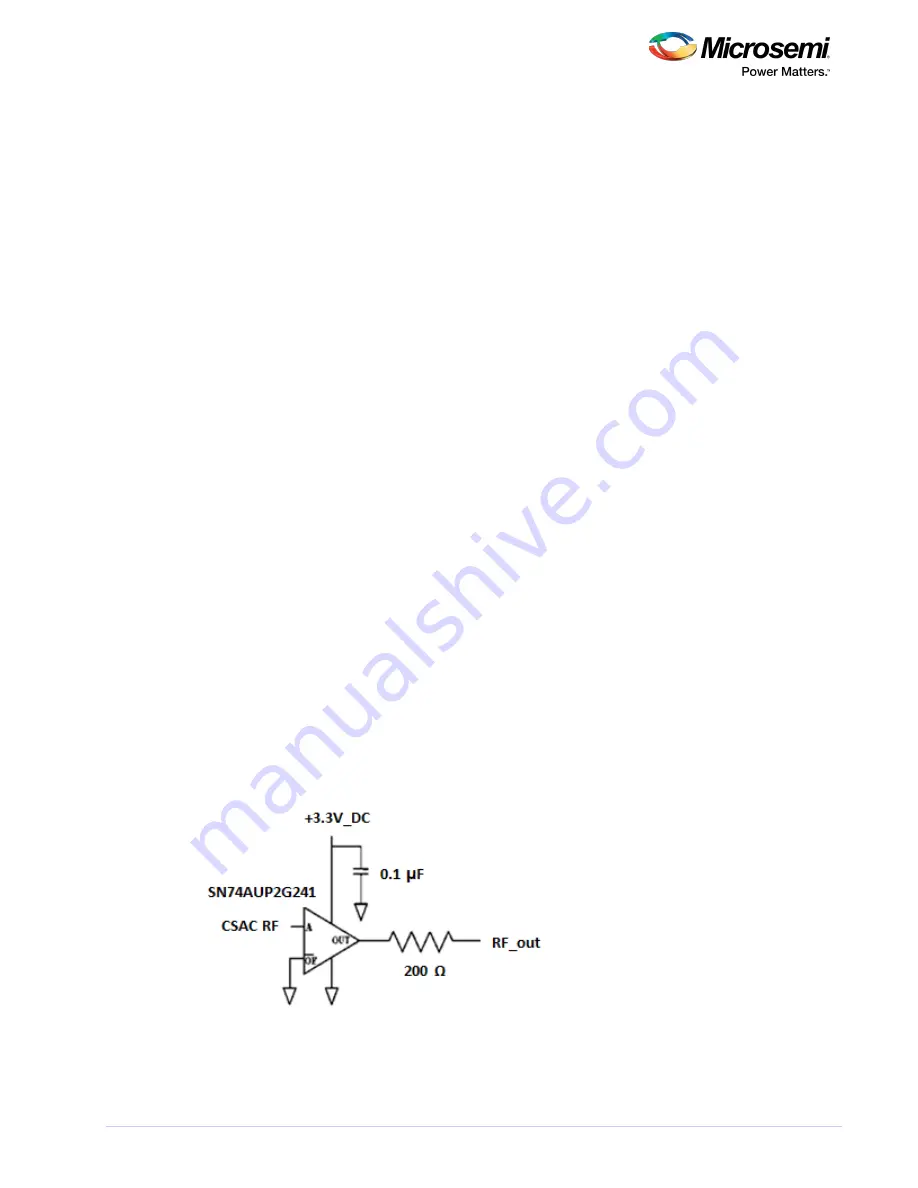
The buffered CMOS RF output is provided on pin 12 of the SA.45s CSAC. The output series impedance is
200 Ω. For reference, the output driver circuit of the SA.45s is shown in the following illustration.
Figure 4 • CSAC RF Output Driver Circuit
The SA.45s is designed for embedded low-power applications—it is expected to drive a high impedance
input, not a 50 Ω measurement instrument or transmission line.
Note: Driving a 50 Ω line at 13 dBm consumes nearly as much power as the CSAC itself. If a high-level
Содержание SA.45s
Страница 1: ...User Guide SA 45s Chip Scale Atomic Clock...


