

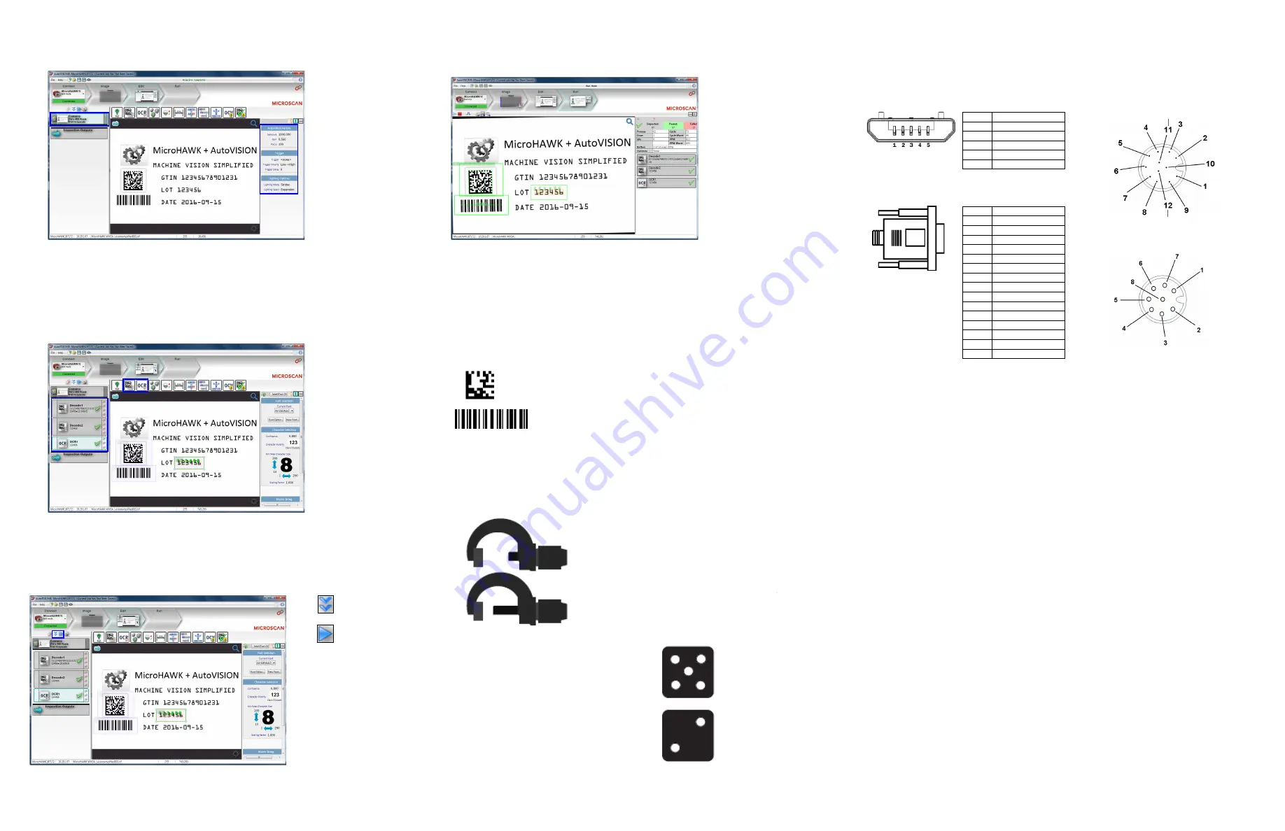
Step 12 — Run the Job
When all job parameters are set, click on the
Run
step at the top of the interface. The software will download the
vision job just created to the camera and will begin the inspection. Inspection results and the list of active tools
are shown at the right of the image view. That information can also be moved below the image area by
clicking the orientation buttons above the inspection results area.
Test Jobs
Note:
For descriptions of more advanced functionality, such as setting
Inspection Outputs
or using the
Locate Tool
and
Decode Tool
’s
Dynamic Locate
functionality to track multiple tools from image to image,
see the help documentation in AutoVISION software
.
Decode Tool, OCR Tool, Match Strings Tool,
String Format Tool
Measure Tool,
Count Tool
LOT 123456
DATE 05/2024
VISION
SIMPLIFIED
Measure:
Measure the distance between
the jaws of the caliper gauges at left.
Count:
Count the circles on the dice shown
at right.
Step 9 — Set Camera Parameters
1. Click on the
Camera
box to the left of the image area.
2. In the camera parameters below the image area, select the desired type of
Trigger
,
Trigger Polarity
,
Photometry
(Exposure and Gain),
Focus
, and
Lighting
.
Step 10 — Add Tools to the Job
1. Click on the
Decode Tool
or drag it onto the image area.
2. Use the anchor points at the corners of the region of interest to form a box around the Data Matrix
symbol. Leave plenty of space on each side of the symbol.
3. Now add a second Decode Tool and do the same for the 1D symbol below the Data Matrix symbol.
4. Finally, add an
OCR Tool
and drag the region of interest around the area of the image where “123456”
is printed.
Step 11 — Try Out the Job
Once you have configured the tools as desired, use the arrow icons in the Job area to try the job you have
just created.
Note:
Most jobs will inspect multiple captured images. If only one image is being inspected, the effect of the
arrow icons will not be evident.
Try Out Job
Once
Try Out Job
in Loop
Copyright ©2017 Microscan Systems, Inc.
Power Requirements and Pin Assignments
MicroHAWK MV-20:
5VDC ± 5%; 350mA at 5VDC (typ.)
MicroHAWK MV-30:
5V ± 5%; 600mA at 5VDC (typ.)
MicroHAWK MV-40:
4.75V – 30V; 150mA at 24VDC (typ.)
Important:
See the MicroHAWK MV-20 / MV-30 / MV-40 Configuration Guide
for information about
Microscan’s
Isolation Mounting Kit (P/N 98-9000064-01)
to eliminate ground loops or other external
electrical noise through your MicroHAWK MV-30 or MV-40 camera.
MicroHAWK MV-20 Micro-USB Type B Socket
Pin
Function
1
Vbus (5V)
2
D–
3
D+
4
N/C
5
Ground
MicroHAWK MV-30 High-Density 15-Pin Dsub
USB/Serial Socket
MicroHAWK MV-40 M12 Connectors
Pin
Function
1
+5VDC
2
TX232
3
RX232
4
GND
5
D+
6
N/C
7
Output 1+
8
9
10
D–
11
Output 3+
12
Input+ (New )
13
Chassis
14
Output 2+
15
Vbus
Ground
Output 3
Output 1
Output 2
New Master
Default
Power
Input Common
Output Common
RS-232 (Host) RxD
Trigger
RS-232
(Host) TxD
M12 12-pin Plug
Note:
An accessory
cable is required
between the MV-30’s
15-pin corner-exit
cable and the host’s
USB port.
TX (+)
RX (–)
RX (+)
TX (–)
V+
V–
M12 8-Pin Socket (Ethernet)
V+
V–
MicroHAWK MV Part Numbers
MicroHAWK MV part numbers follow the format
7ABX-YZZZ-LPPP
.
7 = MicroHAWK
.
Example Part Number: 7412-2000-2104
Description:
MicroHAWK MV-40, IP65 Case, 24V, Ethernet, Machine Vision, SXGA, 1.2 Megapixel, Mono, High Density,
Autofocus, White Outer LEDs, Auto Verifi Visionscape.
(A) Model
1:
Engine, No Case, USB
2:
MV-20, IP40 Case, USB
3:
MV-30, IP54 Case, 5V, USB
4:
MV-40, IP65 Case, 24V, Ethernet
(B) Application Type
1:
Auto ID and Machine Vision
(X) Sensor
1:
WVGA 0.3 Megapixel, Mono
2:
SXGA, 1.2 Megapixel, Mono
3:
QSXGA, 5 Megapixel, Color
(Y) Optics
0:
Custom
1:
Standard Density
2:
High Density
(ZZZ) Focus Distance
000:
Autofocus
050:
50 mm = 1.96 in.
102:
102 mm = 4.02 in.
190:
190 mm = 7.48 in.
300:
300 mm = 11.81 in.
(L) Illumination
0:
Inner LEDs Only
1:
Red Outer LEDs
2:
White Outer LEDs
(PPP) Software License Bundles
100:
AutoVISION Sensor
101:
AutoVISION
102:
Auto Visionscape
103:
Auto Verification
104:
Auto Verifi Visionscape
Notes:
•
(A) Model:
The MicroHAWK Engine is available for OEM-certified partners only.
•
(L) Illumination:
Outer LEDs provide extra illumination. Base level illumination included with all cameras.
•
Field Upgrades:
Not available for optics or illumination due to factory settings for optical alignment, LED balancing, and
sealing for IP enclosure rating. However, the camera’s software is field-upgradeable via licenses.


