

Step 4 — Install AutoVISION
AutoVISION can also be installed from the
Download Center
found on the Microscan Tools Drive that is packaged with the camera.
1. Follow the prompts to install AutoVISION from the Tools Drive.
2. Click on the AutoVISION icon to run the program.
Minimum System Requirements
• Intel Core i3 Processor @ 1.6 GHz
• Internet Explorer 11 or higher / Google Chrome
• 2GB RAM (Windows 7 SP1 / Windows 7 Embedded Standard SP1)
• 3GB hard drive space
• 32-bit color display, 1366 x 768
• 4.0 Windows Experience Index (particularly for graphics)
• 1 USB 2.0 port and 1 Network port
Step 3 — Mount and Position the Camera
1. Position the camera at a focal distance of one inch or more from a test object.
2. Tip the camera relative to the object to avoid the glare of direct (specular) reflection. The case parting
line should be perpendicular to the plane of the symbol by either pitching the symbol or the camera.
Avoid excessive skew or pitch. Maximum skew is ±30°; maximum pitch is ±30°.
Proper lighting is critical to the success of a machine vision application. Depending on the requirements
of your application, you may need to add external lighting from Microscan’s NERLITE family of machine
vision lighting products.
Consider the following:
• Is the surface of the object flat, slightly bumpy, or very bumpy?
• Is the surface matte or shiny?
• Is the object curved or flat?
• What is the color of the object or area being inspected?
• Is the object moving or stationary?
Machine vision lighting should maximize contrast of the areas or features being inspected while
minimizing the contrast of everything else.
Step 5 — Connect to the Camera
After you launch AutoVISION, you will see the
Select a device to start editing a job
view.
Note:
If there is a default job on the camera, AutoVISION will automatically skip the
Connect
step and you
will see the
Image
view.
1. Select your camera from the
Select Device
dropdown menu.
2. Click the
Modify
button beneath the camera settings details to change camera settings.
3. Choose whether you want to create a new job, load a job (.avp), or upload a job from the camera.
Note:
If you are using an MV-20 or MV-30 with a USB cable, the driver has already configured your
PC address. If you are using an MV-40, you must set the PC to the same IP range as the default IP
address. Default IP address:
192.168.188.2
. Set the PC to the same IP range (example:
192.168.188.100
).
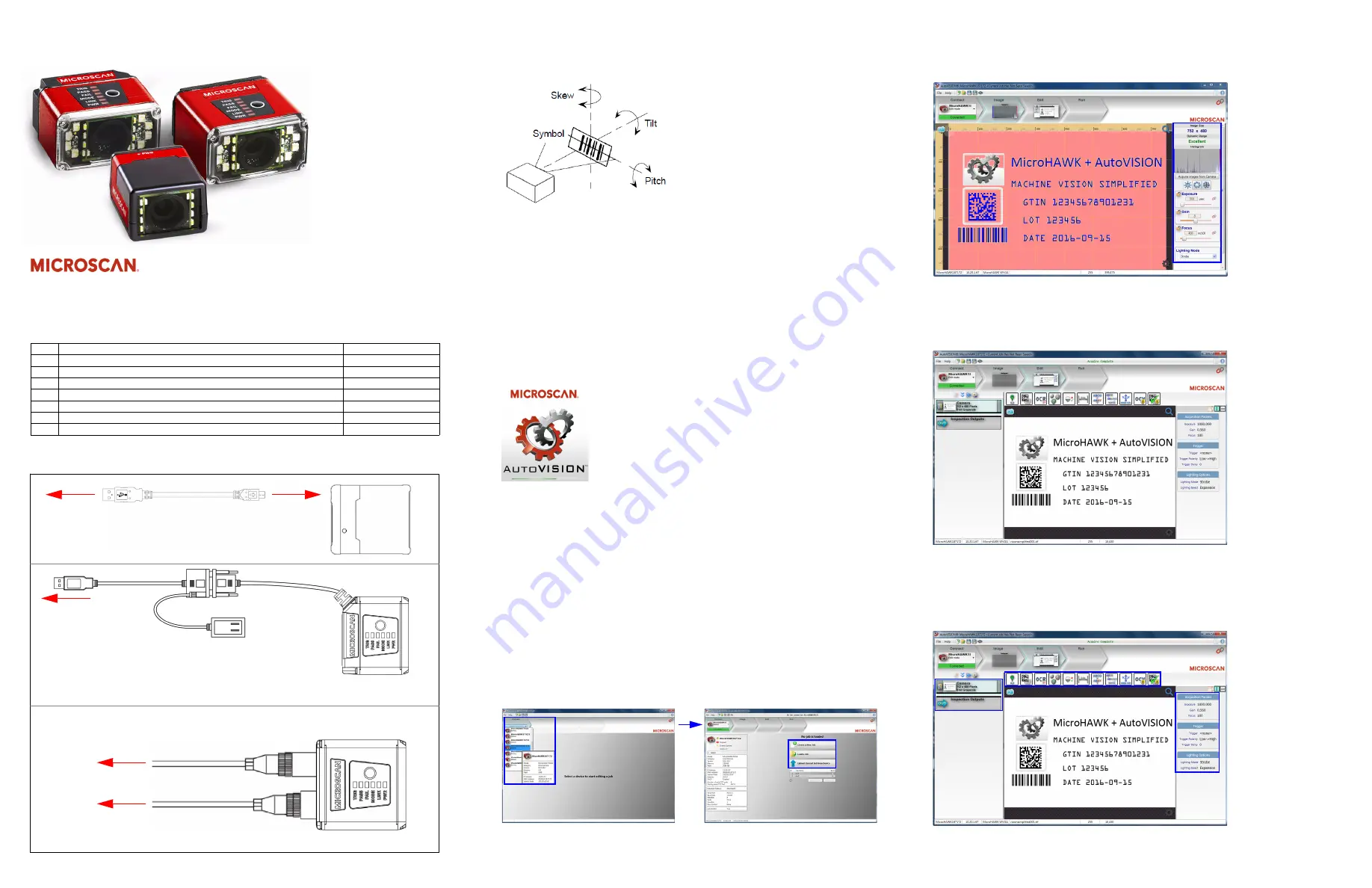
Step 6 — Evaluate a Captured Image and Auto Calibrate
You will see the
Image
view after selecting your device. This view allows you to evaluate your first image
capture, providing information such as image size and a histogram. Click the
Auto Calibration
button to
set optimal camera parameters automatically. You can also adjust
Exposure
,
Gain
, and
Focus
as needed,
and set the desired
Lighting Mode
.
Step 7 — Create Your First Job with AutoVISION
After you have evaluated a captured image and Auto Calibrated the camera in the
Image
view, you will
move to the
Edit
view. This interface allows you to set camera parameters, add machine vision tools to
captured images, set tool parameters, and configure I/O inspection outputs.
Step 8 — Explore the Interface
The
Edit
view features a large image area with tool icons above and tool parameters below or to the right
depending on user preference. When a tool is selected, its specific parameters appear.
Tools that have been added are shown in the job list to the left of the image area, below
Camera
.
Image settings can be controlled using the icons in the corners of the image area.
Note:
A
Color Tool
is also
available, but is not shown in
these images. The Color
Tool proves Color ID and
Color Match functionality.
Quick Start Guide
MicroHAWK MV-20 / MV-30 / MV-40
Copyright ©2017 Microscan Systems, Inc. P/N 83-9137432-02 Rev B
Step 1 — Check Hardware
Note:
Full configuration diagrams are available in the
MicroHAWK MV-20 / MV-30 / MV-40 Configuration Guide.
Item Description
Part Number
1
MicroHAWK MV-20, MicroHAWK MV-30, or MicroHAWK MV-40
7AXY-YZZZ-LPPP
2
Cable, USB A to Micro B, 6 ft., MV-20
61-9000034-01
3
Cable, USB A to Micro B, 3 ft., MV-20
61-9000045-01
4
Power Supply, 5V
97-9000006-01
5
Cable, DB15 to Ext. Power/USB, MV-30
61-9000038-01
6
Power Supply, 100-240VAC, +24VDC, M12 12-Pin Socket
97-000012-01
7
Cordset, Host, Ethernet, M12 8-Pin Plug (Screw-On) to RJ45, 1 m.
61-000160-03
Step 2 — Connect the System
MV-20 – Standalone USB Configuration
To Host
USB Type A
Plug
Micro-USB
Type B Plug
1
2 or 3
MV-30 – Standalone USB Configuration
1
1
MV-40 – Standalone Ethernet Configuration
To Power
Note:
An accessory USB cable is required
between the 15-pin corner-exit cable and
the host’s USB port.
To Host
To Host
Power
Supply
Integrated
Corner-Exit
Cable
Accessory
USB Cable
to Host
Note:
The MV-40 can be configured as an RS-232 camera with the QX-1 Interface Device.
See the
MicroHAWK MV-20 / MV-30 / MV-40 Configuration Guide
for more detail.
5
4
6
7
Note:
There are two USB connection options – one is BUS-powered
and the other is externally powered. BUS-powered cable delivers
reduced illumination – approximately 30% less brightness.