background image

 Workstation 4 Setup Guide

A-1

Appendix A

Equipment Dimensions

In this appendix

Workstation 4 - Low Profile ............................................................A-2
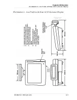
Workstation 4 - LP /w Integrated LCD Customer Display .......... A-3
Workstation 4 on Adjustable Stand .............................................. A-4
WS4 on Adjustable Stand with Rear LCD Customer Display..... A-5
Workstation 4 on Adjustable Stand /w VFD Customer Display .. A-6
Workstation 4 on Wall Mount Stand............................................. A-7
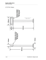
LCD Pole Display ........................................................................... A-8
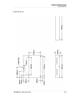
Cash Drawer................................................................................... A-9
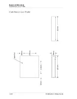
Cash Drawer, Low Profile ............................................................ A-10
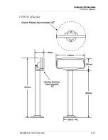
VFD Pole Display ......................................................................... A-11

Содержание Workstation 4

Страница 1: ...micros Systems Inc Workstation 4 Setup Guide Copyright 2003 2004 By MICROS Systems Inc Columbia Maryland USA All Rights Reserved Part Number 100016 117 4th Edition ...

Страница 2: ...ystems Inc National Semiconductor and a registered trademark and Geode is a trademark of National Semiconductor Corporation Microsoft Windows and Windows CE are trademarks of Microsoft Corporation in the United States of America and in other countries Adobe Photoshop and FrameMaker are either registered trademarks or trademarks of Adobe Systems Incorporated in the United States of America and or o...

Страница 3: ...kstation Mountnig Options 1 4 The Adjustable Stand 1 4 Wall Mount Bracket 1 5 Pole Stand 1 6 Adjustable Mounting Arm 1 7 Customer Display Options 1 8 VFD Customer Display 1 8 LCD Customer Display 1 9 Software Components 1 10 Boot Loader 1 10 Windows CE NET 1 10 POS Application 1 10 MICROS Serial Application Loader 1 10 MICROS Client Application Loader 1 11 New WS4 Installation 1 11 Day to Day Oper...

Страница 4: ...d 2 16 Optional PCMCIA Daughter Card 2 17 Rear LCD Customer Display 2 18 Pole LCD Customer Display 2 20 Disk On Chip 2 22 Reassembling the Workstation 4 2 24 Chapter 3 Installing the Workstation 4 Care and Handling 3 2 Equipment Placement 3 2 Location 3 2 Proximity to Foreign Materials 3 2 Noise Induction 3 3 Electrostatic Discharge 3 3 Temprature and Humidity 3 3 AC Power and Data Cabling Require...

Страница 5: ... 5 Running the WS4 Diagnostics Utility 4 5 The System Information Screen Hardware Components 4 6 The System Information Screen Software Components 4 8 Workstation 4 Wipe Compact Flash WCF Utility 4 12 Appendix A Equipment Dimensions Workstation 4 Low Profile A 2 Workstation 4 Low Profile with Rear LCD Customer Display A 3 Workstation 4 on Adjustable Stand A 4 WS4 on Adjustable Stand with Rear LCD ...

Страница 6: ... B 7 Hook up Cables B 8 RS232 from the RS422 A and RS422 B Ports B 8 LCD Customer Display Cables B 9 System Board Integrated Cable B 9 LCD Customer Display Assembly Interface Cable B 9 Remote Pole LCD Customer Display B 10 Ethernet B 11 Ethernet Cross over Pinning B 12 8 Pin to 6 Pin Hook up RS422 Cable 300319 001 B 13 Cash Drawer Extension Cable B 14 Appendix C FCC DOC Statement ...

Страница 7: ...eface you ll find information about this manual Refer to the preface if you have questions about the organization conventions or contents of this manual In this section Why Read This Manual viii How This Manual Is Organized ix Notation Conventions x ...

Страница 8: ...Preface Why Read This Manual Why Read This Manual Purpose This guide is intended for those who will be setting up installing and operating the MICROS Workstation 4 WS4 and as such is not specific to a particular software application ...

Страница 9: ... hardware configuration Topics include how to remove the cover identify and upgrade the major components Chapter 3 covers the WS4 installation from arranging cables at the connector panel to using the Client Application Loader to connect to the system POS server and obtain the application software Chapter 4 provides basic troubleshooting data in the form of BIOS error messages and beep codes A Ref...

Страница 10: ... CorelDraw NOTE This symbol brings special attention to a related item WARNING This symbol indicates that specific handling instructions or procedures are required to prevent damage to the hardware or loss of data SHOCK HAZARD This symbol calls attention to a potential hazard that requires correct procedures in order to avoid personal injury STATIC SENSITIVE DEVICES This symbol indicates that spec...

Страница 11: ...station 4 This chapter describes the Workstation 4 and accessories and discusses the various software components In this chapter The System 1 2 Software Components 1 10 Memory Architecture 1 14 Power Management States 1 18 Specifications 1 21 Approvals 1 22 ...

Страница 12: ...ure 1 1 The Workstation 4 Standard features include a 12 inch Active Matrix LCD 5 wire resistive touchscreen and integrated 3 Track Mag Stripe Reader Operator LCD and Touchscreen The Operator Liquid Crystal Display is 12 1 in size and runs at a resolution of 800x600 and is capable of supporting up to 64K colors The touchscreen glass is a Microtouch 3M 5 wire resistive touchscreen Magnetic Card Rea...

Страница 13: ... POS application system registry and optionally Stand Alone Resilient SAR totals In other words it contains the personality of the workstation Should the workstation fail the CF card can be removed and installed in the replacement workstation Optional PCMCIA PC Card Bus Slot The WS4 includes an optional PCMCIA Card Bus Slot Windows CE device driver support for the PCMCIA slot is limited so all PC ...

Страница 14: ...gure 1 3 converts the low profile WS4 into an adjustable display design The stand has a weighted base for stable operation and self locking hinges that allow the workstation to be tilted in a range of between 25 and 70 degrees The base includes holes for mounting the VFD Pole Display Bracket shown in Figure 1 3 In addition the Workstation 4 base is compatible with the existing User Workstation 3 a...

Страница 15: ...an exit from the side rear or bottom as shown in Figure 1 4 below Figure 1 4 Adjustable Stand Cable Management Wall Mount Bracket In addition to the Adjustable Display stand a flexible wall mount bracket is available as shown below in Figure 1 5 Figure 1 5 The Wall Mounting Bracket The wall mount bracket can be used to place the WS4 on a wall or to suspend the unit under a counter or custom cabine...

Страница 16: ...a cable opening at the base The adjustable section allows the height of the workstation to be positioned between approximately 12 and 16 inches from the counter surface The mounting plate is non adjustable and fixed at an angle of 115 The workstation is placed in the VESA Compatible Mounting Adapter which in turn is fastened to VESA compatible hole centers in the Pole Stand Mounting Plate The VESA...

Страница 17: ...WS4 shown in the illustration below Figure 1 7 The Adjustable Mounting Arm It can be used to mount the WS4 to a counter surface wall or under a shelf The VESA compatible mounting bracket attaches to the adjustable mounting arm plate and the WS4 is attached to the adapter See the WS4 Product Marketing Announcement PMA for information on pricing and part numbers ...

Страница 18: ...is composed a 2 Line 20 Character Vacuum Fluorescent Display VFD Two pole mount versions are available It is mounted to a pole approximately 6 in length that in turn is secured to the WS4 Adjustable Stand with a customer made bracket This version is shown in Figure 1 8 Figure 1 8 VFD Pole Display Mounted to the Adjustable Stand A full size version of the VFD Pole Customer Display is shown in Figur...

Страница 19: ... power and data from the system board The upper portion of Figure 1 10 shows the LCD display mounted to an WS4 LP left or to a WS4 placed on the Adjustable Stand right The lower half of Figure 1 10 displays several views of the pole mount version of the LCD customer display This version receives power and data from a 4 pin Mini DIN connector on the workstation IO panel Both the Integrated and Pole...

Страница 20: ... Windows CE Platform Builder CEPB that allows MICROS to custom build an operating system using with only the modules and drivers required to support the WS4 hardware and application software This results in an operating system where the memory footprint and CPU requirements are substantially less than a traditional desktop operating system POS Application The Workstation 4 is a hardware platform c...

Страница 21: ...stallations there will be only one CAL server When the CAL server is selected the installer is presented with a list of workstations pre programmed in the application s device database When the installer selects a workstation from the list the WS4 name and TCP IP network configuration DHCP or Static IP Address are entered in the workstation s registry The CAL then transfers the application package...

Страница 22: ...ow or deferring to a later time If the operator chooses to complete the update now the updated files are retrieved and copied over the application on the CF card Upon completion the workstation is restarted Windows CE Operating System Update During its routine check for updated applications on the system server the CAL Client also checks for an update to the Operating System OS An updated OS becom...

Страница 23: ...nd optionally SAR data The registry contains configuration data including the WS4 name TCP IP network settings and the number and type of peripherals installed This allows the replacement workstation to take on all of the characteristics of the defective workstation without the need to restore recovery images When the CF card is installed in the replacement workstation and the unit powered up the ...

Страница 24: ...OS image file NK BIN placed there by the CAL as part of an upgrade If the OS image file is not found the Boot Loader copies the current OS image located on the DOC into system RAM and starts it If the NK BIN is found it is copied over the existing OS image on the DOC replacing it The NK BIN file is deleted by the CAL after the upgrade process is complete The OEM Adaptation Layer OAL is a collectio...

Страница 25: ...L file and allows POS Applications to access hardware such as the cash drawers mag stripe reader and the various customer display options The WS4 Drivers consists of a collection of DLL files that provide access to WS4 hardware including the LCD network power button and the persistent registry Compact Flash CF Card The Compact Flash CF Card represents the removable component of the WS4 mass storag...

Страница 26: ...nd a LAN connection to the system server is established POS Application software that supports SAR will use a portion of the CF card to store off line transaction totals SDRAM Working System RAM System or working RAM is contained in a single 168 Pin DIMM socket Currently a 128M PC133 168 Pin 3 3V unbuffered SDRAM is populated in socket DIMM1 The contents are shown in Figure 1 15 below Figure 1 15 ...

Страница 27: ...ty swap Should a WS4 fail the CF card can be removed and installed in a replacement unit giving it the same configuration as the inoperative workstation from which it was removed Even though the Workstation 4 is diskless in the classical sense the combination of the Disk On Chip and CF card provide a mass storage solution to preserve application and registry settings that require a lifetime that e...

Страница 28: ...WER The AC power cable is attached but the operating system and applications are not running RAM contents are undefined The Operator LED is Off ON Windows CE and POS application is operating RAM contents are maintained The Operator LED is solid Green SUSPEND Windows CE and POS application is not running RAM contents are maintained Restoring the unit from SUSPEND restores the LCD screen and content...

Страница 29: ...the power button for less than 5 seconds SUSPEND 7 ON WS4 Application The application shuts down the workstation NOPOWER 8 ON WS4 Application The application places the WS4 in SUSPEND state SUSPEND 9 SUSPEND Operator The operator presses the power button for less than 5 seconds ON 10 SUSPEND Operator The operator presses the power button for more than 5 seconds NOPOWER 11 SUSPEND Server Applicatio...

Страница 30: ...e Workstation 4 Power Management States Workstation 4 Power Management State Diagram Figure 1 17 shows the workstation power states Numbers in bubbles correspond to the left column in Figure 1 16 Figure 1 17 WS4 Power Management State Diagram ...

Страница 31: ...emory One 168 Pin DIMM socket supports 32 MB to 256 MB of PC133 SDRAM 3 3V Unbuffered Mag Stripe Reader 3 Track ABA compatible operates in MAGTEK and Special modes Customer Displays Optional 2 x 20 VFD or 240x64 graphics based LCD available in both integrated and pole mount versions USB Ports Two external UHCI 1 1 compliant USB ports LAN Interface On Board National DP83815 Ethernet Controller supp...

Страница 32: ... 4 meets the following safety and environmental certifications Directive Specification Year Expiration Date Comments SAFETY EN60950 2000 7 1 06 EMC EN 55022 1998 Current A1 2000 Radiated EN 55024 1998 Current A1 2001 EN 61000 3 2 2000 Current Harmonics EN 61000 3 3 1995 Current A1 2001 Flicker ...

Страница 33: ...on provides a description of the system board and peripheral boards shows how to install options then shows how to reassemble the unit In this chapter Disassembling the Workstation 4 2 2 System Board 2 7 LCD Touchscreen and Mag Stripe Reader Assembly 2 14 Hardware Updates 2 16 Reassembling the WS4 2 23 ...

Страница 34: ...th on your work surface to protect the LCD and touchscreen glass then place the workstation face down on this surface o The WS4 cover is held in place by a pair of screws accessible from the underside of the unit as shown in the top half of Figure 2 1 A pair of hinges are located at the rear of the base Figure 2 1 Figure 2 1 WS4 Cover Hinges and Screws SHOCK HAZARD When the AC Power Cable is conne...

Страница 35: ...of the base a little to release them then lift up If you lift up on the cover without first releasing the hinges you can break them 5 Raise the rear of the cover and remove the toroid mounted to the RF shield as shown in Figure 2 2 The toroid is fastened to a cable held in place on the RF shield with a pair of clips Figure 2 2 Removing the Mag Stripe Reader Cable Toroid 6 When you remove the toroi...

Страница 36: ...he Magnetic Stripe Reader Cable modular connector from its system board socket o Remove the backlight cable from the backlight board o Remove the touchscreen cable from the touchscreen extension cable o Remove the customer display cable from the Rear LCD Display if this option is installed o Remove the LVDS cable from the LVDS board on the Samsung LCD or directly from the Sharp LCD panel Figure 2 ...

Страница 37: ...uide 2 5 What s Inside Disassembling the Workstation 4 Figure 2 4 Removing Cables from the Top Cover Sharp LCD 9 Remove the RF shield First remove the five screws shown in Figure 2 5 Figure 2 5 Removing the RF Shield screws ...

Страница 38: ... from the LVDS cable by releasing the latch as shown in Figure 2 6 Figure 2 6 Removing the LVDS Cable from the Toroid 11 Lift up to remove the RF shield and take care to avoid damaging the LVDS or Backlight Cable Figure 2 7 shows the workstation with the RF shield removed and points out system board and power supply Figure 2 7 Workstation with RF Shield Removed ...

Страница 39: ...is section shows the system board components connectors and jumpers A block diagram and brief technical description is also included Main Components Figure 2 8 shows the major components of the Workstation 4 system board Figure 2 8 Workstation 4 System Board Main Components ...

Страница 40: ...2 8 Workstation 4 Setup Guide What s Inside System Board Connectors Figure 2 9 shows the Workstation 4 System Board connectors Figure 2 9 Workstation 4 System Board Connectors ...

Страница 41: ...Workstation 4 Setup Guide 2 9 What s Inside System Board Jumpers and Switches Figure 2 10 points out the system board jumpers and switches Figure 2 10 System Board Jumpers and Switches ...

Страница 42: ...3200 The SC3200 is now a member of the Advanced Micro Devices AMD WebPAD on a Chip family of highly integrated x86 system devices AMD purchased National Semiconductor Corporation Geode processor line in 2003 The SC3200 consists of a GX1 processor core integrated with a TFT LCD video controller x86 PC compatible core logic and super IO The features of this chip are listed below GX1 266MHz 32 bit x8...

Страница 43: ...amily and a companion to the Geode SC3200 Outstanding features of the device include Low Pin Count LPC Interface to the SC3200 PS 2 Keyboard and Mouse Controller Two Serial Ports One Parallel Port LED Driver Up to 45 General Purpose IO pins In the WS4 these pins are dedicated to RS422 RS232 Serial port control and Complex Programmable Logic CPLD Device Control DP83815 Ethernet Controller The Natio...

Страница 44: ... to start In addition the CF card must not be removed or inserted when power is on Like the DOC the Windows CE operating system views the card as a Windows file system The workstation initially shipped with a 32M part and switched to a 64M part in early 2004 Larger sizes may be used but always consult the approved CF card list located in the hardware support section of the MICROS web site The CF c...

Страница 45: ... streams A Phase Lock Loop PLL clock is transmitted in parallel with the data streams over a forth data stream This device and the companion LVDS receiver provide a means to reduce the EMI emissions normally associated with wide high speed TTL interfaces to active LCD panels Touchscreen Interface The WS4 Touchscreen Interface consists of micro controller U37 Touchscreen Controller U38 and serial E...

Страница 46: ...op cover In addition to the Backlight Inverter and Mag Stripe Reader assembly the upper half shows the Samsung LTM121SI T01 LCD panel used in production units up to July August 2004 The lower half shows the replacement a Sharp LQ121S1LG41 Note the absence of the LVDS receiver board on the Sharp LCD the equivalent circuitry is built into the panel Figure 2 12 Top Cover Assembly ...

Страница 47: ...d is no longer required A new interface cable between the system board and LCD panel is required Backlight Inverter Board The Backlight Inverter Board is mounted to the LCD bracket Both the Samsung and Sharp LCD panels use the same backlight inverter board It receives 10 4VDC and a Pulse Width Modulation PWM signal from the system board to control backlight brightness Magnetic Card Reader The 3 tr...

Страница 48: ...s not required Removal and Installation 1 Remove the WS4 Cover 2 Remove the system board RF shield 3 Locate the CF Daughter card and remove the screws shown in Figure 2 13 Figure 2 13 Removing the Compact Flash Daughter Card 4 Lift up on the daughter card to remove it from its system board socket then pull it slightly forward to allow the CF socket to clear the I O panel bracket 5 To reinstall the...

Страница 49: ...rd socket Figure 2 14 PCMCIA Daughter Card Installation 5 Install the PCMCIA Card in the Daughter Card 6 Position the daughter card so that the PCMCIA card will project from the I O bracket slot When the holes in the card line up with each stand off press down on the daughter card to seat it in J18 7 Install screws in each stand off as shown on the right side of Figure 2 14 8 Reinstall the RF shie...

Страница 50: ... pre installed on WS4s shipped after May 2004 S N 4083019472 o If the cable is not installed proceed to Step 4 otherwise continue with the next step 3 Connect the cable from the LCD Display assembly to the cable protruding through the opening in the shield cover Figure 2 15 Skip to Step 8 Figure 2 15 Connecting the LCD Customer Display 4 Obtain display interface cable P N 400416 007 5 Remove the R...

Страница 51: ...WS4 configured to run the e7 POS Application includes the necessary drivers to support the LCD Customer Display However the majority of WS4s currently in the field as of September 2004 are running the GR1 0 or GR1 1 software platform If connected to a WS4 running GR1 0 or GR1 1 the LCD customer display will not function An upgrade to GR1 2 or later is required to support the 2x20 VFD emulation mod...

Страница 52: ...ed on the counter surface the installer must provide mounting hardware for the base The cable length is approximately 5 feet 1 Use the base as a template to locate the mounting holes in the counter surface 2 After mounting the pole display base to the counter surface route the extension cable through the pole and connect the LCD assembly cable Figure 2 18 Mount the LCD assembly to the pole positio...

Страница 53: ...to support the Rear Pole LCD Customer Display However the majority of WS4s currently in the field as of September 2004 are running the GR1 0 or GR1 1 software platform If connected to a WS4 running GR1 0 or GR1 1 the LCD customer display will not function An upgrade to GR1 2 or later is required to support the 2x20 VFD emulation mode In addition the graphics features of the display are not yet sup...

Страница 54: ...you can see in Figure 2 20 below the DOC is somewhat larger than the socket Figure 2 20 Disk On Chip Mounting To void damaging the socket or delicate DOC pins as you remove it the series of illustrations in Figure 2 21 show how to use a flat blade screw driver to gently lift one side of the DOC then the other before removing the DOC from its socket Figure 2 21 Disk On Chip Removal ...

Страница 55: ...left o If installed route the optional customer display cable through the opening at the center of the RF shield o Route the LVDS cable through the opening on the top of the shield Reinstall the toroid on the cable and place the toroid cable in the holders as shown o The touchscreen extension cable should project from the opening in the front of the shield o The backlight cable should exit the shi...

Страница 56: ...tly in front of the base 6 Connect the following cables to the top cover Figure 2 24 o Touchscreen ribbon cable to the keyed touchscreen extension cable projecting from the front of the shield o LVDS cable to the LVDS Receiver Board on the Samsung LCD Figure 2 24 or directly to the Sharp LCD Panel Figure 2 25 and the Backlight Cable to the Backlight Inverter Board WARNING Before continuing take a ...

Страница 57: ...e WS4 o Insert the modular connector on the Mag Stripe Reader Cable through the cut out in the shield and attach it to the system board connector Figure 2 24 Connecting Cables to the Top Cover Samsung LCD Figure 2 25 Connecting Cables to the Top Cover Sharp LCD ...

Страница 58: ...e WS4 7 Before closing the cover place the toroid on the mag stripe reader cable in the cable clamps mounted to the shield Figure 2 26 Figure 2 26 Securing the Mag Card Reader Cable to the RF Shield 8 Tighten the cover screws to secure the top cover to the base ...

Страница 59: ...hapter 3 Installing and Operating the Workstation 4 This chapter describes how to install and the operate the Workstation 4 In this chapter Care and Handling 3 2 The IO Panel 3 5 Installation 3 7 Operation 3 10 Personality Swap 3 16 ...

Страница 60: ...nt is carpeted an anti static grade is recommended If the carpeting surrounding the area containing the equipment is not composed of anti static material the use of static discharge mats should be considered An anti static mat incorporates a grounding clip with a cable to provide a discharge path to ground Proximity to Foreign Materials WARNING Do not use sharp objects such as a pen or pencil to p...

Страница 61: ...However tile or anti static carpet should still be employed in areas near the workstation Temperature and Humidity The Workstation 4 can operate in temperatures between 32 F and 113 F 0 C to 45 C A constant humidity between 40 and 90 is required for proper operation of the equipment Before applying power to the unit ensure that its temperature is within 15 F 8 C of room temperature to prevent dama...

Страница 62: ...or clean lint free cloth to clean the cabinet and touchscreen surface Do not use chemical alcohol or petroleum based cleaners that are not recommended for plastics Magnetic Card Reader Depending on how much they are used magnetic card readers may require periodic cleaning MICROS recommends cleaning the heads once a day if the reader is subjected to heavy usage Cleaning kits are available from a va...

Страница 63: ...e Workstation 4 PMA or your MICROS representative for more information about compatible PCMCIA cards Compact Flash CF The Compact Flash Card CF is factory populated on a daughter card and is accessible from the I O Panel In a compromise between security and accessibility the CF card is protected by a bracket fastened to the case with two hex screws After the WS4 is installed and in operation the C...

Страница 64: ...e connectors support standard and low profile MICROS cash drawers with DIN style connectors PS 2 Keyboard and Mouse The keyboard port supports a standard PS 2 style keyboard The mouse port supports a PS 2 style mouse or other pointing device Customer Display This connector supports a pole mount Remote Customer Display The Display contains a two line display with twenty characters per line The disp...

Страница 65: ...heavier than most peripheral cables and will serve as the strength member for the entire bundle 2 Connect each peripheral cable to the appropriate I O connector Bundle each peripheral together with the AC power cable and attach two tie wraps to the bundle as shown on the right side of Figure 3 1 Figure 3 1 Securing the AC Power Cable and Bundling the Peripheral Cables Figure 3 1 shows two tie wrap...

Страница 66: ... the stand as shown in Figure 3 2 The workstation will slide down and lock into place Figure 3 2 Attaching the WS4 to the Stand 4 Tilt the workstation to the fully reclined position and install the pair of thumbscrews supplied with the stand to secure it to the workstation Figure 3 3 Figure 3 3 Securing the Workstation to the Stand 5 Place your peripherals near the workstation and attach cables as...

Страница 67: ... Installing and Operating the Workstation 4 Installation 6 Connect the AC power cord to an electrical outlet installed in accordance with the appropriate site prep guide See the Starting the Workstation for the first time procedure ...

Страница 68: ...atures Operator LCD The Operator LCD is an 12 1 Active Matrix Display with a resolution of 800x600 The 5 wire resistive touchscreen glass is positioned over the LCD Power Switch The power switch is used by the operator to transition the Workstation 4 between the various power management states Operator LED The Operator LED displays the current power state and is capable of displaying three colors ...

Страница 69: ...ates that the workstation is proceeding with the boot process The Windows CE operating system will start in approximately 60 seconds Figure 3 5 Workstation 4 Boot Splash Screen When the workstation completes booting to the operating system the Operator LED turns solid Green If you are starting the WS4 as part of a new installation see the section entitled Starting the Workstation for the First Tim...

Страница 70: ... is older than the version of CAL on the server CAL will update itself before proceeding to download the application The Workstation proceeds to download the application package and automatically reboots when complete When the reboot is complete the CAL automatically starts the application Using SUSPEND The Workstation 4 can be placed in SUSPEND by the operator when it will not be used for a perio...

Страница 71: ... on the cover Figure 3 6 shows how to insert the card and pull it through the reader slot past the reader head Figure 3 6 Using the Magnetic Card Reader Tips for using Magnetic Cards Magnetic cards should always be kept dry and away from magnets or sharp objects that could damage the encoded information on the card If a mag card is damp or wet or appears damaged in any way DO NOT insert into the r...

Страница 72: ...ardware Support section of the web site Never remove or insert the CF card when AC power is connected The System Board and CF Daughter Card are not provisioned to support hot swapping Always remove the AC power cable from the workstation before inserting or removing the CF card for any reason The CF card is a keyed device it can only be installed one way but it is possible to force the card into i...

Страница 73: ... the Touchscreen directly If the workstation is on a stand adjust it to the optimum viewing angle Procedure 1 From the desktop press or click Start Settings Control Panel press or click the Touchscreen icon twice to start the calibration program The Touchware Properties window appears From this window you can also make other touchscreen related adjustments 2 Press the Calibrate button A calibratio...

Страница 74: ...I O panel These tie wraps must be removed before a workstation can be replaced Procedure 1 Remove all cables from the inoperative workstation s I O panel including the AC Power Input If may be helpful to create a diagram of where each cable is connected as you remove it If a cable is fastened to the cable cleats with tie wraps use the wire cutters to clip them If the WS4 is mounted to the optional...

Страница 75: ...te the keying lip on the bottom of the card and the guides that hold it in place Figure 3 8 Compact Flash Card Removal 5 Remove the CF card from the inoperative WS4 Use your thumbnail or pen to catch the lip and remove the card from the socket Figure 3 8 Hold on to this card it must be inserted into the replacement WS4 6 Un box and remove the packing material from the replacement WS4 If a CF card ...

Страница 76: ...milar to that shown in Figure 3 9 will be added to the CF card after July 2003 Note the arrow showing the proper orientation of the card Figure 3 9 CF Personality Card Label If the label is not present Figure 3 10 denotes the location of a lip that can also assist you in orienting the card as it is installed Figure 3 10 CF Personality Card Orientation ...

Страница 77: ...ing and Operating the Workstation 4 Personality Swap 7 Install the personality card removed from the inoperative WS4 Refer to Figure 3 11 it displays a series of illustrations describing how insert the card Figure 3 11 Inserting the CF Card ...

Страница 78: ...e card in until it is fully inserted It does not require a great deal of force to insert the card If it does recheck the orientation of the card before proceeding 8 Re install the CF card bracket and fasten with the pair of screws 9 Re cable the replacement WS4 Reconnect each cable to the appropriate I O connector When complete this unit will be ready for use 10 Install the CF card removed from th...

Страница 79: ...de 4 1 Chapter 4 Workstation 4 Diagnostics This chapter includes diagnostics information on the Workstation 4 In this chapter Basic Troubleshooting 4 2 Power On Self Test POST Errors 4 3 Workstation 4 Diagnostics Utility 4 5 ...

Страница 80: ... swipe WS4 is in Suspend mode Press the power button for two seconds then release it Display should be restored The Beeper Sounds once Operator LCD displays blue screen but multiple beeps are reported Operator LED is blinking Red four times per second 25Hz Power On Self Test POST Error See POST Section Replace WS4 The Beeper Sounds once Operator LCD displays blue screen but hangs before booting Op...

Страница 81: ...eep code sounds once the WS4 halts and does not respond to the power button You must remove then reconnect the AC power cable to restart the unit If the POST in Boot Loader V2 0 09 or later encounters a problem the error code sounds three times and halts but the WS4 responds to the power button Please note that WS4 Diagnostic Utility versions prior to 1 87 do not display the Boot Loader version co...

Страница 82: ...card Note 4 If the POST indicates a touchscreen controller failure make sure there are no objects such as a pencil or pen on the screen Cleaning the screen or placing an object on the touchscreen during the POST can cause the touchscreen controller to fail Note 5 The POST SDRAM test toggles each bit in each memory location by reading and writing 0xAA and 0x55 patterns The test will not detect a mi...

Страница 83: ...tor LCD to assist in detecting hot or cold pixels Version 1 90 Included with GR 1 2 o System Info Dump A new button on the System Info screen writes all values to a text file called WS4Dump txt on the root of the CF Card o Rear and Pole LCD Customer Display Support New tests include Backlight Control Contrast Adjust Pixel ON OFF Reset firmware version reporting and firmware upgrades The LCD Custom...

Страница 84: ...software platform components A brief description of the hardware components follows Diagnostic Version This field displays the WS4 Diagnostic Utility Software Version Hardware Revision This field displays the WS4 System Board hardware revision It is read directly from the system board by the WS4 API Most current units in the field will include Revision D through G system board There is very little...

Страница 85: ...ware therefore the CPLD Version field refers to the firmware version running on that device The CPLD firmware can only be changed using a specialized parallel port programmer attached to system board connector J16 The factory and authorized repair centers have this capability Boot Loader Version The Boot Loader is located on the WS4 system Board Greater detail can be found in the system board tech...

Страница 86: ...ng system software utilities such as the CAL and the software platform files described in greater detail in the following section Physical Address This field displays the network Media Access Control MAC number assigned to the system board Ethernet Controller at the factory Each workstation will display a unique value in this field Motherboard Serial Number This field displays a 19 digit serial nu...

Страница 87: ...face POS Applications use the API to access hardware such as the Cash Drawers Mag Stripe Reader and IDN Interface The GR 1 2 platform updates uws4 dll with many new features to support the graphics based LCD customer display UWS4Power DLL This driver controls the power button while WinCE is running It polls the system board CPLD every 150 milliseconds checking for switch closures and transitions t...

Страница 88: ... POS applications to access the system board beeper At boot time the Boot Loader controls the beeper WinCE Version The current Microsoft WinCE Version number MICROS Build Version The MICROS Build version represents the combination of the WinCE operating system and it s internal drivers An internal driver is not accessible in the same manner as the WS4 platform drivers located on the DOC but are in...

Страница 89: ...osition To disable the keyboard press the pencil icon again and select Hide Input Panel from the menu that appears Testing the WS4 Many of the tests are self explanatory or include on screen help To perform a Cash Drawer test apply the following formula to the six digit number that appears when you attempt to access the test Digit 1 x Digit 2 Digit 4 Digit 6 Access Code For example if the number i...

Страница 90: ...during testing Erase Compact Flash This selection erases the entire contents of the CF card including the persistent registry folder the POS application and SAR totals if present After execution of either selection WCF restarts the WS4 using the factory default register settings The default registry starts the CAL client and assuming the CAL server is configured properly a new or updated applicati...

Страница 91: ...ervices that the application programmer can call upon to access the POS features of the Workstation 4 For example to open a cash drawer the programmer calls an API function The API determines which system board is installed and selects the appropriate register and bit in the CPLD to open the drawer Changes to a register port address or a new version of the system board is handled by the API and th...

Страница 92: ...asks as checking the CF card for OS image updates managing the Operator LED and controlling backlight brightness CAL Abbreviation for Client Application Loader The MICROS CAL is a software utility that assists in the installation of the Workstation 4 application software then manages the ongoing maintenance of the operating system and application software The CAL consists of two parts one part res...

Страница 93: ... processing depending on which POS application software is in use COM Port A type of IO Port that is generally referred to as a serial interface or asynchronous communications port This type of IO port transmits information to and from the computer in a serial fashion one bit at a time CPLD Abbreviation for Complex Programmable Logic Array The WS4 system board uses one of these devices custom prog...

Страница 94: ...utility programs such as diagnostics and the MICROS CAL IDN Abbreviation for Integrated Device Network Also referred to in previous MICROS documentation as the Stand alone Device Network or Remote Printer Networks The MICROS IDN is based on a full duplex RS422 interface designed to support MICROS Stand alone Printers and Video Display Units connected in a multi drop or daisy chain configuration ID...

Страница 95: ...ternate design an active matrix puts a transistor at every pixel When a small current is sent through it the transistor switches on providing a much higher current to activate the LCD pixel Active matrix LCDs are more expensive than passive displays but are many times brighter and can be viewed from greater angles LVDS Abbreviation for Low Voltage Deferential Signalling Magnetic Stripe Card A plas...

Страница 96: ...e SDRAM where it can be accessed and manipulated by the CPU The bootloader and WinCE OS manage this See also SDRAM Operating System System software that acts as a master control program to manage the execution of application programs The kernel or core of the operating system remains in memory to receive user input as well as to provide an interface to the hardware Operating systems perform other ...

Страница 97: ...tral repository for all hardware and software configuration information for the Windows operating system and applications When Windows CE is running the registry is located in RAM where it can be quickly accessed When the OS or application examines modifies or creates a registry entry it occurs in the RAM version called the Working registry A driver called the Persistant Registry Driver PRD period...

Страница 98: ...nd beyond RS232 The RS422 specification defines signal lines and voltage levels and is issued by the Electronics Industry Association and Telecommunications Industry Association A full duplex version of RS422 is used by the Workstation 4 to drive IDN printing devices The workstation has two RS422 ports RTC Abbreviation for Real Time Clock The RTC is connected to a battery and separate crystal osci...

Страница 99: ...Magnetic Stripe Reader input mode which buffers track data into the API allows the POS application to detect that the MSR track data is available then allows the application to retrieve MSR data for processing See Also MAGTEK Mode System Board The motherboard or mainboard for the Workstation 4 The System Board contains the majority of the workstation circuitry including the CPU Chipset SDRAM Disk ...

Страница 100: ...s simultaneous data access between a host computer and a wide range of peripherals The USB carries data using a host scheduled token based protocol that provides a total bandwidth of 1 5MB s or 12 MB s over a daisy chain of up to 128 peripheral devices The WS4 includes two USB 1 0 compatible ports Currently only a USB keyboard and mouse are supported ...

Страница 101: ...LP w Integrated LCD Customer Display A 3 Workstation 4 on Adjustable Stand A 4 WS4 on Adjustable Stand with Rear LCD Customer Display A 5 Workstation 4 on Adjustable Stand w VFD Customer Display A 6 Workstation 4 on Wall Mount Stand A 7 LCD Pole Display A 8 Cash Drawer A 9 Cash Drawer Low Profile A 10 VFD Pole Display A 11 ...

Страница 102: ...A 2 Workstation 4 Setup Guide Equipment Dimensions Workstation 4 Low Profile Workstation 4 Low Profile ...

Страница 103: ...Workstation 4 Setup Guide A 3 Equipment Dimensions Workstation 4 Low Profile with Rear LCD Customer Display Workstation 4 Low Profile with Rear LCD Customer Display ...

Страница 104: ...A 4 Workstation 4 Setup Guide Equipment Dimensions Workstation 4 on Adjustable Stand Workstation 4 on Adjustable Stand ...

Страница 105: ...Workstation 4 Setup Guide A 5 Equipment Dimensions WS4 on Adjustable Stand with Rear LCD Customer Display WS4 on Adjustable Stand with Rear LCD Customer Display ...

Страница 106: ...A 6 Workstation 4 Setup Guide Equipment Dimensions Workstation 4 on Adjustable Stand with VFD Pole Display Workstation 4 on Adjustable Stand with VFD Pole Display ...

Страница 107: ...Workstation 4 Setup Guide A 7 Equipment Dimensions Workstation 4 on Wall Mount Stand Workstation 4 on Wall Mount Stand ...

Страница 108: ...A 8 Workstation 4 Setup Guide Equipment Dimensions LCD Pole Display LCD Pole Display ...

Страница 109: ...Workstation 4 Setup Guide A 9 Equipment Dimensions Cash Drawer Cash Drawer ...

Страница 110: ...A 10 Workstation 4 Setup Guide Equipment Dimensions Cash Drawer Low Profile Cash Drawer Low Profile ...

Страница 111: ...Workstation 4 Setup Guide A 11 Equipment Dimensions VFD Pole Display VFD Pole Display ...

Страница 112: ...A 12 Workstation 4 Setup Guide Equipment Dimensions VFD Pole Display ...

Страница 113: ...hat follow you will find diagrams of the Workstation 4 I O Panel connectors system board connectors and commonly used hook up cables A description of how each cable or connector is used is provided In this appendix IO Panel Connectors B 2 System Board Connectors B 7 Hook up Cables B 8 ...

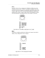
Страница 114: ...onfiguration of these ports is the RS422 based IDN mode The RS422 A port is configured as COM4 and the RS422 B port is configured as COM5 Either port is capable of driving MICROS IDN printing devices if supported by POS applications such as 9700 or 3700 Figure B 1 shows the pin out for this configuration Figure B 1 LCC Connector Configured for IDN Printing WARNING Do not insert a 6 Pin modular plu...

Страница 115: ...h the Serial Application Loader SAL to directly replace the UWS 3 in 8700 and 9700 installations MD0006 025 describes how to replace a UWS 3 with a WS4 in 9700 installations support for 8700 installations was pending at the time this manual was released Figure B 2 LCC Connector Configured in LCC mode RS232 The RS422 A COM4 and RS422 B COM5 ports include a basic RS232 interface This configuration i...

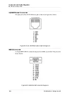
Страница 116: ...10 100 Ethernet Connector The pin out for the 10 100 Ethernet port is shown in Figure B 4 below Figure B 4 10 100 Ethernet Connector Diagram RS232 Connector A single DB9F RS232 connector assigned to COM1 is provided The pin out is shown below Figure B 5 DB9 RS232 Connector Diagram ...

Страница 117: ...Cable Diagrams IO Panel Connectors USB Connectors A pair of USB ports are located on the IO panel shown in Figure B 6 below Figure B 6 Universal Serial Bus Connector Diagram Cash Drawer 1 and 2 Connectors Figure B 7 Cash Drawer Connector Diagram ...

Страница 118: ...onnectors PS2 Mouse Keyboard Connectors Figure B 8 PS2 Mouse and Keyboard Connector Diagrams Remote Customer Display Connector This port supports either the 2x20 VFD customer display or the graphics based LCD customer display Figure B 9 Customer Display Connector Diagram ...

Страница 119: ...nectors This section details connectors located on the Workstation 4 system board Magnetic Stripe Interface The internal magnetic card reader connector is CN10 located on the system board The pin outs for this connector are shown in Figure B 10 Figure B 10 System Board Magnetic Card Reader Connector ...

Страница 120: ... the RS422 A and RS422 B Ports Figure B 11 shows a cable that includes the RS232 signals from RS422 A and RS422 B ports to a DB9 male connector This cable is available from MICROS by ordering P N 300319 102 Figure B 11 Modular LCC RS232 to DB9 Male Connector Figure B 12 shows a cable diagram that adapts the same RS422 A and RS422 B ports to a DB25 connector Figure B 12 Modular LCC RS232 to DB25 Co...

Страница 121: ...4 Figure B 13 System Board to Rear LCD Customer Display LCD Customer Display Assembly Interface Cable The LCD Customer Display Assembly includes the LCD Display Housing which in turn consists of LCD Panel Interface Board mounting bracket and interface cable A diagram of this interface cable is shown in Figure B 14 The only difference between the Rear and Pole versions of the LCD customer display h...

Страница 122: ...CD Customer Display This cable shown in Figure B 15 is supplied with the Pole LCD Customer Display kit It attaches between the 4 pin DIN customer display connector on a WS4 or KWS4 IO Panel up through the pole to mate with the cable from the LCD Display Assembly shown in Figure B 14 Figure B 15 Remote Pole LCD Customer Display Assembly ...

Страница 123: ...able Diagrams Hook up Cables Ethernet Figure B 16 shows a diagram of a standard Cat 5 Ethernet hook up cable This cable would be connected from a workstation or server to the system hub Figure B 16 EIA TIA 568 A Cat 5 Ethernet Hook up Cable Diagram ...

Страница 124: ...gram of a typical Category 5 hook up cable with the transmit receive cross over pinning implemented This cable can be used when only two devices must be connected For example it can be used to connect two workstations or a server connected to a single client Figure B 17 Cat 5 Ethernet Hook up Cable Diagram cross over ...

Страница 125: ...p Cables 8 Pin to 6 Pin Hook up RS422 Cable 300319 001 This cable brings out the RS422 signals from the 8 pin LCC RS232 connector to a 6 pin wall plate or directly to the 6 pin connector located on the IDN device Figure B 18 8 Pin to 6 Pin RS422 Hook up Cable Diagram ...

Страница 126: ...B 14 Workstation 4 Setup Guide Connector and Cable Diagrams Hook up Cables Cash Drawer Extension Cable ...

Страница 127: ...e limits for a Class A computing device pursuant to Subpart J of Part 15 of FCC Rules which are designed to provide reasonable protection against such interference when operated in a commercial environment Operation of this equipment in a residential area is likely to cause interference in equipment in which case the user at his own expense will be required to take whatever measures may be require...

Страница 128: ...es dépassant les limites applicables aux appareils numériques de Classe A de Classe B selon le cas prescrites dans Le Règlement sur le Brouillage Radioélectrique Idicté par le Ministère des Communications du Canada Caution Changes or modifications not expressly approved by the party responsible for compliance could void the user s authority to operate the equipment Shielded interface cables must b...

Отзывы: