Communications
Chapter 3
))))))))))))))))))))))))))))))))))))))))))))
))))))))))))))))))))))))))))))))))))))))))))
410 Operators Manual
16
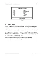
Parallel Port Configuration
1 = /STROBE
2 = D0
3 = D1
4 = D2
5 = D3
6 = D4
7 = D5
8 = D6
9 = D7
10 = /ACK
11 = BUSY
12 = PAPER OUT
13 = SLCT
14 = NC
15 = /ERROR
16 = /INIT
17 = NC
18-25 = GROUND
(25 PIN FEMALE)
Table 3
3.2
PRINTER CABLES
Warning: Connection of a serial printer to a parallel port may result in damage to the printer
and/or computer. Connection of a parallel printer to a serial port may result in damage to the
printer and/or computer.
The printer cables needed are standard and available through Microcom Corporation. You will
not need a NULL-modem cable because the printer is DCE equipment.
For parallel connection, use a straight 25 pin male to 25 pin male cable, connected from the
desired parallel port of the host computer to the 25 pin connector on the optional parallel board.
For serial connection, if your host computer has a...
25 pin serial com port - Use a standard 25 pin male to 9 pin male serial cable.
9 pin serial com port - Use a 9 pin female to 9 pin male video extension cable.
Содержание 410
Страница 8: ... 410 Operators Manual 2 ...
Страница 14: ... 410 Operators Manual 8 ...
Страница 93: ...Chapter 5 Printer Commands 410 Operators Manual 87 190 CLOSE 200 SYSTEM ...
Страница 97: ...Chapter 5 Printer Commands 410 Operators Manual 91 2 80 column Epson emulation 4 inch ...
Страница 104: ...Printer Commands Chapter 5 410 Operators Manual 98 Notes ...


