


3.
How to Get Calibration Values
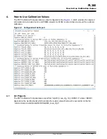
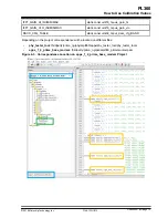
Microchip provides a Python script named "phycalibrationtool.py" in order to get optimal calibration values
implied in the signal emission characterization which could affect to the ripple, amplitude and impedance
algorithm detection used by firmware on G3 and PRIME protocol implementations (
Requirements for phycalibrationtool.py can be found in
6. Appendix B - Requirements for
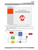
This application works over phy_tester_tool firmware, so this project example must be running on the
host microcontroller of PL360 board.
Along the test process, the PLC signal may be connected to different impedance loads; therefore, it is
strongly recommended to uncouple the PLC signal as far as possible from the mains power supply of the
device under test (
Figure 3-1. Calibration Setup
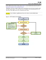
The Physical Calibration process implies the following steps:
•
Initialization: set default equalization and gain calibration values used by PHY Calibration Tool
•
Equalization: the objective is to get a flatter frequency response of the signal on the band in use; for
that a maximum ripple must be defined below the customer limits; as general rule, Microchip
recommends a margin of 0'5-1dB in order to handle the different impedance load of the
equalization performed
•
Gain Calibration: the objective of gain calibration is to get the desired signal power in a range of
variable gain for AUTO GAIN mode. An initial gain must be defined and customer must decide
minimum and maximum values for AUTO GAIN mode. The minimum value could impact on the
performance of VLOW mode when emitting against high impedance if the system can't emit low
enough to maintain the signal on the PLC line. After modifying gain it is strongly recommended to
measure the ripple again in order to check if has been affected due to non-linearity when using a
high level of power
•
Max RMS Level Process: the process gets the target RMS values for each Transmission mode
•
Thresholds Process: the process calculates the threshold values in order to pass between
Transmission modes (high to VLOW and opposite)
PL360
How to Get Calibration Values
©
2018 Microchip Technology Inc.
User Guide
DS50002818A-page 8


