


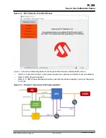

2.
Physical Layer Capabilities
The firmware implementation for G3 and PRIME protocols make use of the following concepts in
relationship with the transmission and reception stages:
•
Transmission Modes
•
Impedance Detection
•
Equalization
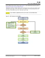
2.1
Transmission Modes
Transmission modes are configurations applied to the PHY layer in order to improve the performance,
efficiency and spectrum ripple of the output driver according to the impedance detected in the line.
Depending on the detected impedance, two Transmission modes are defined:
•
HI_STATE. Mode optimized for high impedance (Z > 20Ω)
•
VLO_STATE. Mode optimized for very low impedance (Z < 10Ω)
Additionally, the PHY layer can modify the signal gain in a way that offers optimum results when
combined with the Transmission mode. This behavior is controlled by the PIB
PHY_PARAM_CFG_AUTODETECT_BRANCH. There are three operation modes:
•
FIXED_STATE_FIXED_GAIN: Transmission mode and gain are fixed
•
FIXED_STATE_VAR_GAIN: Transmission mode is fixed but the gain is managed by the Automatic
Gain Control (AGC) block to achieve signal level injection target
•
AUTO_STATE_VAR_GAIN: Transmission mode and gain are managed dynamically to optimize the
output according to the line impedance and signal level injection target
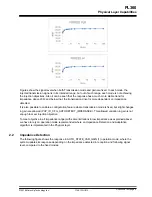
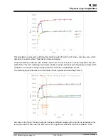
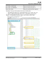
Since each Transmission mode is optimized within an impedance range, it doesn't work properly in terms
of performance/efficiency when operating outside such range. Let’s suppose we have set a signal
injection objective of 110 dBuV for both HI and VLO modes. The following figures show the response of
forced modes in an impedance range from 0 to 50Ω.
PL360
Physical Layer Capabilities
©
2018 Microchip Technology Inc.
User Guide
DS50002818A-page 4


