


2003 Microchip Technology Inc.
Preliminary
DS41206A-page 57
PIC16F716
9.2
Oscillator Configurations
9.2.1
OSCILLATOR TYPES
The PIC16F716 can be operated in four different
oscillator modes. The user can program two
configuration bits (FOSC1 and FOSC0) to select one of
these four modes:
• LP - Low-power Crystal
• XT - Crystal/Resonator
• HS - High-speed Crystal/Resonator
• RC - Resistor/Capacitor
9.2.2
CRYSTAL OSCILLATOR/CERAMIC
RESONATORS
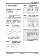
In XT, LP or HS modes, a crystal or ceramic resonator
is connected to the OSC1/CLKIN and OSC2/CLKOUT
pins to establish oscillation (Figure 9-1). The
PIC16F716 oscillator design requires the use of a
parallel cut crystal. Use of a series cut crystal may give
a frequency out of the crystal manufacturers
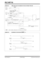
specifications. When in XT, LP or HS modes, the
device can have an external clock source to drive the
OSC1/CLKIN pin (Figure 9-2).
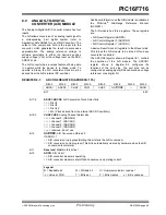
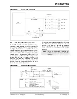
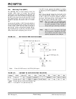
FIGURE 9-1:
CRYSTAL/CERAMIC
RESONATOR OPERATION
(HS, XT OR LP
OSC CONFIGURATION)
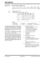
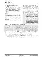
FIGURE 9-2:
EXTERNAL CLOCK INPUT
OPERATION (HS, XT OR
LP OSC
CONFIGURATION)
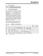
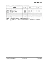
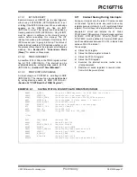
TABLE 9-1:
CERAMIC RESONATORS
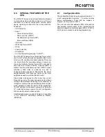
TABLE 9-2:
CAPACITOR SELECTION FOR
CRYSTAL OSCILLATOR
Note 1:
See Table 9-1 and Table 9-2 for
recommended values of C1 and C2.
2:
A series resistor (RS) may be required.
3:
RF varies with the crystal chosen.
C1
(1)
C2
(1)
XTAL
OSC2
OSC1
RF
(3)
Sleep
To
logic
PIC16F716
RS
(2)
internal
OSC1
OSC2
Open
Clock from
ext. system
PIC16F716
Ranges Tested:
Mode
Freq
OSC1 (C1)
OSC2 (C2)
XT
455 kHz
2.0 MHz
68-100 pF
15-68 pF
68-100 pF
15-68 pF
HS
4.0 MHz
8.0 MHz
16.0 MHz
10-68 pF
15-68 pF
10-22 pF
10-68 pF
15-68 pF
10-22 pF
Note 1:
These values are for design guidance
only. See notes at bottom of page.
Osc Type
Crystal
Freq
Cap. Range
C1
Cap. Range
C2
LP
32 kHz
15-33 pF
15-33 pF
200 kHz
5-10 pF
5-10 pF
XT
200 kHz
47-68 pF
47-68 pF
1 MHz
15-33 pF
15-33 pF
4 MHz
15-33 pF
15-33 pF
HS
4 MHz
15-33 pF
15-33 pF
8 MHz
15-33 pF
15-33 pF
20 MHz
15-33 pF
15-33 pF
Note
1:
These values are for design guidance only.
See notes at bottom of page.
Note 1: Higher capacitance increases the stability
of the oscillator, but also increases the
start-up time.
2: Since each resonator/crystal has its own
characteristics, the user should consult
the resonator/crystal manufacturer for
appropriate values of external
components.
3: RS may be required to avoid overdriving
crystals with low drive level specification.
4: When using an external clock for the
OSC1 input, loading of the OSC2 pin
must be kept to a minimum by leaving the
OSC2 pin unconnected.
Содержание PIC16F716
Страница 6: ...PIC16F716 DS41206A page 4 Preliminary 2003 Microchip Technology Inc NOTES...
Страница 35: ......
Страница 56: ......
Страница 60: ......
Страница 88: ......
Страница 92: ...PIC16F716 DS41206A page 90 Preliminary 2003 Microchip Technology Inc NOTES...
Страница 108: ...PIC16F716 DS41206A page 106 Preliminary 2003 Microchip Technology Inc NOTES...
Страница 110: ...PIC16F716 DS41206A page 108 Preliminary 2003 Microchip Technology Inc NOTES...
Страница 124: ...PIC16F716 DS41206A page 122 Preliminary 2003 Microchip Technology Inc NOTES...


