MRF24WN0MA/MB
DS50002410A-page 12
Advance Information
2015 Microchip Technology Inc.
2.3
SPI Port Pins
The MRF24WN0MA/MB module interfaces to the
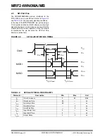
PIC32 MCU via a 4-wire SPI port. Refer to
Figure 2-2
and
Table 2-2
for the necessary signaling conditions.
In the case of the SPI_CS/MODE1 pin, pull-up using a
10 k
resistor and the host MCU allows an active-high
signal during power on and wake-up to ensure that the
module start-up in normal operation. Once the module
is operational, the pin becomes the SPI Port Chip
Select pin (active-low).
FIGURE 2-2:
SPI SLAVE INTERFACE TIMING
TABLE 2-2:
SPI SLAVE TIMING CONSTRAINTS
Parameter
Description
Min.
Max.
Unit
f
PP
Clock Frequency
0
48
MHz
t
WL
Clock Low Time
8.3
—
ns
t
WH
Clock High Time
8.3
—
ns
t
TLH
Clock Rise Time
—
2
ns
t
THL
Clock Fall Time
—
2
ns
t
ISU
Input Setup Time
5
—
ns
t
IH
Input Hold Time
5
—
ns
t
O
_
DLY
Output Delay
0
5
ns
Clock
MOSI
MISO
V
IH
V
IL
V
IH
V
IL
V
OH
V
OL
f
PP
t
WL
t
WH
t
TLH
t
THL
t
ISU
t
IH
t
O_DLY(max)
t
O_DLY(min)
Содержание MRF24WN0MA
Страница 14: ...MRF24WN0MA MB DS50002410A page 14 Advance Information 2015 Microchip Technology Inc NOTES...
Страница 30: ...MRF24WN0MA MB DS50002410A page 30 Advance Information 2015 Microchip Technology Inc NOTES...
Страница 32: ...MRF24WN0MA MB DS50002410A page 32 2015 Microchip Technology Inc NOTES...
Страница 34: ...MRF24WN0MA MB DS50002410A page 34 Advance Information 2015 Microchip Technology Inc NOTES...


