


MIC2125/6
DS20005459B-page 22
2015 Microchip Technology Inc.
5.4
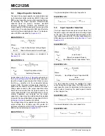
Output Capacitor Selection
The type of the output capacitor is usually determined
by its equivalent series resistance (ESR). Voltage and
RMS current capability are two other important factors
for selecting the output capacitor. Recommended
capacitor types are ceramic, tantalum, low-ESR
aluminum electrolytic, OS-CON, and POSCAP. The
output capacitor’s ESR is usually the main cause of the
output ripple. The output capacitor ESR also affects the
control loop from a stability point of view. The maximum
value of ESR is calculated by
EQUATION 5-13:
The required output capacitance is calculated in
.
EQUATION 5-14:
As described in the
subsection of
the
, the MIC2125/26 requires at
least 20 mV peak-to-peak ripple at the FB pin to ensure
that the g
m
amplifier and the comparator behave
properly. Also, the output voltage ripple should be in
phase with the inductor current. Therefore, the output
voltage ripple caused by the output capacitors value
should be much smaller than the ripple caused by the
output capacitor ESR. If low-ESR capacitors, such as
ceramic capacitors, are selected as the output
capacitors, a ripple injection method should be applied
to provide the enough feedback voltage ripple. Refer to
the
subsection for details.
The voltage rating of the capacitor should be twice the
output voltage for a tantalum and 20% greater for
aluminum electrolytic or OS-CON. The output capacitor
RMS current is calculated in
.
EQUATION 5-15:
The power dissipated in the output capacitor is:
EQUATION 5-16:
5.5
Input Capacitor Selection
The input capacitor reduces peak current drawn from
the power supply and reduces noise and voltage ripple
on the input. The input voltage ripple depends on the
input capacitance and ESR. The input capacitance and
ESR values are calculated by using
and
.
EQUATION 5-17:
EQUATION 5-18:
The input capacitor should be qualified for ripple
current rating and voltage rating. The RMS value of the
input capacitor current is determined at the maximum
output current. Assuming the peak-to-peak inductor
current ripple is low:
EQUATION 5-19:
The power dissipated in the input capacitor is:
EQUATION 5-20:
ESR
C
OUT
V
OUT PP
I
L PP
---------------------------
Where:
∆
V
OUT(PP)
Peak-to-Peak Output Voltage Ripple
∆
I
L(PP)
Peak-to-Peak Inductor Current Ripple
C
OUT
I
L PP
V
OUT PP
f
SW
8
---------------------------------------------------
=
Where:
C
OUT
Output Capacitance Value
f
SW
Switching Frequency
I
C
OUT RMS
I
L PP
12
------------------
=
P
DISS COUT
I
COUT RMS
2
ESR
COUT
=
C
IN
I
OUT
D
1
D
–
V
IN C
f
SW
-----------------------------------------------
=
Where:
I
OUT
Load Current
ƞ
Power Conversion Efficiency
∆
V
IN(C)
Input Ripple Due to Capacitance Value
ESR
CIN
V
IN ESR
I
L PK
-------------------------
=
Where:
∆
V
IN(ESR)
Input Ripple Due to Capacitor ESR
Value
I
L(PK)
Peak Inductor Current
I
CIN RMS
I
OUT MAX
D
1
D
–
P
DISS CIN
I
CIN RMS
2
ESR
CIN
=


