background image

Explorer 16 Programming Tutorial

©

 2005 Microchip Technology Inc.


DS51589A-page 18

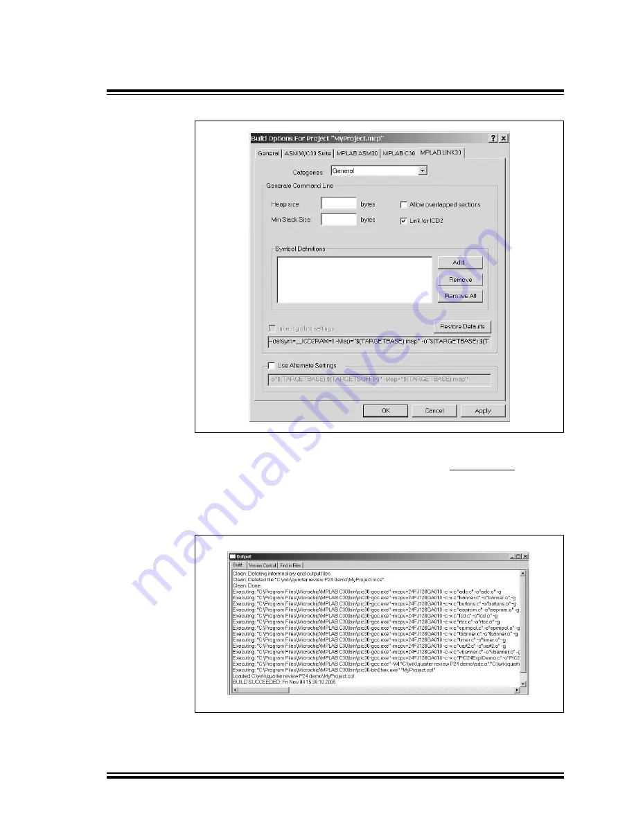
FIGURE 2-8:

MPLAB

®

 LINK30 BUILD OPTIONS

2.5.2

Build the Project

From the menu bar of the main MPLAB IDE window, select 

Project > Make. The Build 

Output window displays (Figure 2-9).

Observe the progress of the build. When the “BUILD SUCCEEDED” message displays, 
you are ready to program the device.

FIGURE 2-9:

BUILD OUTPUT

Содержание Explorer 16

Страница 1: ...2005 Microchip Technology Inc DS51589A Explorer 16 Development Board User s Guide...

Страница 2: ...l other trademarks mentioned herein are property of their respective companies 2005 Microchip Technology Incorporated Printed in the U S A All Rights Reserved Printed on recycled paper Note the follow...

Страница 3: ...ghlights 11 2 3 Tutorial Overview 11 2 4 Creating the Project 12 2 5 Building The Code 16 2 6 Programming the Device 19 Chapter 3 Explorer 16 Tutorial Programs 3 1 Introduction 23 3 2 PIC24 Tutorial P...

Страница 4: ...Explorer 16 Development Board User s Guide DS51589A page iv 2005 Microchip Technology Inc NOTES...

Страница 5: ...onstration program created in Chapter 2 Explorer 16 Programming Tutorial Chapter 4 Explorer 16 Development Hardware provides a more detailed description of the Explorer 16 board s hardware features Ap...

Страница 6: ...ct Enable Programmer Quotes A field name in a window or dialog Save project before build Underlined italic text with right angle bracket A menu path File Save Bold characters A dialog button Click OK...

Страница 7: ...vices Reference information found in this data sheet includes Device memory map Device pinout and packaging details Device electrical specifications List of peripherals included on the device Note tha...

Страница 8: ...ent Environment IDE software THE MICROCHIP WEB SITE Microchip provides online support via our web site at www microchip com This web site is used as a means to make files and information easily availa...

Страница 9: ...ircuit Debuggers The latest information on the Microchip in circuit debugger MPLAB ICD 2 MPLAB IDE The latest information on Microchip MPLAB IDE the Windows Integrated Development Environment for deve...

Страница 10: ...Preface 2005 Microchip Technology Inc DS51589A page 6 NOTES...

Страница 11: ...HAT S IN THE KIT The Explorer 16 Development Board Kit contains the following The Explorer 16 Development Board A preprogrammed PIC24FJ128GA010 Processor Installation Module PIM already installed to t...

Страница 12: ...13 Eight indicator LEDs 14 74HCT4053 multiplexers for selectable crossover configuration on serial com munication lines 15 Serial EEPROM 16 Independent crystals for precision microcontroller clocking...

Страница 13: ...at the PIC24FJ128GA010 PIM is correctly installed onto the board If you want to use the dsPIC device PIM carefully remove the PIC24 PIM and install the dsPIC33F PIM in its place For all PIMs be certai...

Страница 14: ...y devices Separate demo source code as files in C and compiled code files in Hex are provided for each family These may be used with the included PIC24 and dsPIC33F PIMs by reprogramming the devices u...

Страница 15: ...us buttons are pressed Described with the PIC24 project is the dsPIC device tutorial Example1_RTC_LED_ADC mcp It is also written in C for MPLAB C30 The program displays voltage and current time updati...

Страница 16: ...for this tutorial C Tutorial is assumed in the instructions that follow From the Example Code Tutorial Code directory on the Explorer 16 Development Kit Software CD ROM copy all of the source files in...

Страница 17: ...sembler and linker that will be used 2 In the Toolsuite Contents combo box select MPLAB C30 Compiler pic30 gcc exe 3 In the Location box click Browse and navigate to C Program Files Microchip MPLAB C3...

Страница 18: ...CT 2 4 3 Name Your Project 1 In the Project Name text box type MyProject 2 In the Project Directory box click Browse and navigate to C Tutorial to place your project in the Tutorial folder 3 Click Nex...

Страница 19: ...e in the project There should now be two files in the project 5 Click Next to continue 6 When the summary screen displays click Finish After the Project Wizard completes the MPLAB Project window shows...

Страница 20: ...contains additional information that lets you debug the code at the source code level Before building there are settings required to tell MPLAB IDE where to find the include files and to reserve spac...

Страница 21: ...e General tab 2 Click Suite Default This tells the environment where to find the library files 3 Select the MPLAB LINK30 tab to view the linker settings Figure 2 8 4 Check Link for ICD2 5 Click OK The...

Страница 22: ...AB LINK30 BUILD OPTIONS 2 5 2 Build the Project From the menu bar of the main MPLAB IDE window select Project Make The Build Output window displays Figure 2 9 Observe the progress of the build When th...

Страница 23: ...near the top of the main_rtc c file _FGS CODE_WRITE_PROT_OFF _FOSCSEL FRC_PLL _FOSC CSW_FSCM_OFF OSC2_IO XT _FWDT WDT_OFF If configuration macros are not used in the source code it is also possible to...

Страница 24: ...he device MPLAB IDE should report that it found the PIC24FJ128GA010 device as shown in Figure 2 11 FIGURE 2 11 ENABLING MPLAB ICD 2 Note Do not use the Configuration Bits window to set device configur...

Страница 25: ...ogram the Device 1 From the Debugger menu select Program to program the part The Output window Figure 2 12 displays the program steps as they occur 2 Observe the results of the programming When MPLAB...

Страница 26: ...Explorer 16 Programming Tutorial 2005 Microchip Technology Inc DS51589A page 22 NOTES...

Страница 27: ...alternates between Celsius and Fahrenheit values The voltage and temperature are updated continuously This mode also lets users store the current temperature in the on board serial EEPROM by pressing...

Страница 28: ...this set the terminal emulator for 19200 baud 8 bit data 1 Stop bit and no parity check FIGURE 3 1 PIC24 TUTORIAL PROGRAM FLOWCHART Explorer 16 Development Board Power up PIC24 Features Scrolling Ban...

Страница 29: ...and converts the potentiometer signal 0 to 3 3 VDC on analog channel AN5 When a conversion is complete an interrupt is generated and the result in the ADCBUF0 register is copied into a temporary vari...

Страница 30: ...L PROGRAM FLOWCHART dsPIC33 Demo Press S3 to cont Power up Initialize Timer1 Is S3 pressed Initialize A D Converter to Decimal and Call Update_LCD No Update time Update volts Yes Yes No Yes No Convert...

Страница 31: ...2 must always be left in the PIM posi tion In future versions with a permanently mounted PIC24 device at U1 setting S2 in the PIC position will enable the on board device and disable the PIM socket 4...

Страница 32: ...have some 5V tolerant input pins If a 5V tolerant input is connected to the PIC18LF4550 protection diodes on the PIC18LF4550 device s port pins will limit inputs to VDD For more information on which p...

Страница 33: ...3 3V When pressed they are grounded 4 2 10 Analog Input Potentiometer A 10 k potentiometer is connected through a series resistor to AN5 It can be adjusted from VDD to GND to provide an analog input t...

Страница 34: ...n The 30 pin PICtail Plus expansion boards can be used in either the top or middle 30 pin sections The Explorer 16 board provides footprints for two edge connectors for daughter cards one populated J5...

Страница 35: ...D UART1 PINS ON PICtail PLUS INTERFACE Control Pin State UART1 Control Pins SPI1 Control Pin RB14 Control Pin RB13 Control Pin RB12 U1RX U1TX U1CTS U1RTS SDI1 SDO1 1 2 4 19 20 5 7 0 4 2 20 19 7 5 Note...

Страница 36: ...Explorer 16 Development Hardware 2005 Microchip Technology Inc DS51589A page 32 NOTES...

Страница 37: ...LOPMENT BOARD BLOCK DIAGRAM FIGURE A 1 HIGH LEVEL BLOCK DIAGRAM OF THE EXPLORER 16 DEVELOPMENT BOARD PIC24FJ128GA010 dsPIC33FJ256GP710 16x2 LCD Display PIC18LF4550 SPI ICSP JTAG ICD ICSP JTAG RS 232 T...

Страница 38: ...Microchip Technology Inc DS51589A page 34 A 3 DEVELOPMENT BOARD SCHEMATICS FIGURE A 2 EXPLORER 16 BOARD SCHEMATIC SHEET 1 OF 8 PIM SOCKET V DDCORE V CAP V DDCORE VSS VSS VDD 100 Pin PIM V SS V DD V SS...

Страница 39: ...page 35 2005 Microchip Technology Inc FIGURE A 3 EXPLORER 16 BOARD SCHEMATIC SHEET 2 OF 8 BOARD MOUNTED PIC24FJ128GA010 MCU WHEN INSTALLED 10 F 1 F V CAP V DDCORE VDD VSS PIC24FJ128GA010 VDD AV DD V D...

Страница 40: ...ent Board Schematics 2005 Microchip Technology Inc DS51589A page 36 FIGURE A 4 EXPLORER 16 BOARD SCHEMATIC SHEET 3 OF 8 MPLAB ICD 2 JTAG PICkit 2 AND PICtail Plus CONNECTORS MPLAB ICD 2 Connector 1 F...

Страница 41: ...Explorer 16 Development Board User s Guide DS51589A page 37 2005 Microchip Technology Inc FIGURE A 5 EXPLORER 16 BOARD SCHEMATIC SHEET 4 OF 8 PICtail PLUS EDGE AND SOCKET CONNECTORS...

Страница 42: ...orer 16 Development Board Schematics 2005 Microchip Technology Inc DS51589A page 38 FIGURE A 6 EXPLORER 16 BOARD SCHEMATIC SHEET 5 OF 8 SWITCHES MULTIPLEXERS AND POTENTIOMETER VEE VCC 1 F 1 F VCC VEE...

Страница 43: ...hip Technology Inc FIGURE A 7 EXPLORER 16 BOARD SCHEMATIC SHEET 6 OF 8 EEPROM TEMPERATURE SENSOR LEDs OSCILLATOR CIRCUITS AND POWER SUPPLY 1 F 25LC256 1 F TC1047A 22 pF 22 pF 32 kHz 1 F 47 F 1 F 47 F...

Страница 44: ...2005 Microchip Technology Inc DS51589A page 40 FIGURE A 8 EXPLORER 16 BOARD SCHEMATIC SHEET 7 OF 8 USB AND UART SUBSYSTEMS V USB VSS VDD VDD VSS VSS VDD VDD PIC18F4550_QFN44 1 F 1 F 1 F 1 F 1 F 1 F 1...

Страница 45: ...1589A page 41 2005 Microchip Technology Inc FIGURE A 9 EXPLORER 16 BOARD SCHEMATIC SHEET 8 OF 8 LCDs AND OPTIONAL LCD CONNECTIONS Alternative LCD Configurations 4 7 F 4 7 F 4 7 F 4 7 F 1 F 1 F 1 F 1 F...

Страница 46: ...Explorer 16 Development Board Schematics 2005 Microchip Technology Inc DS51589A page 42 NOTES...

Страница 47: ...l the PICkit 2 programmer software Complete instructions for installing and using the programmer software application is provided in the PICkit 2 Microcontroller Programmer User s Guide DS51553 The pr...

Страница 48: ...d click the Open button The progress of the update is displayed in the status bar of the programming software When the update completes successfully the status bar displays Operating System Verified T...

Страница 49: ...onnector 8 28 JTAG Connector 8 30 LCD Alphanumeric 8 28 LCD Graphic 8 29 LEDs 8 29 Multiplexers 8 30 Oscillator Options 8 29 PICkit 2 Connector 8 30 PICtail Plus Card Edge Connectors 8 30 Power Indica...

Страница 50: ...3 China Shenzhen Tel 86 755 8203 2660 Fax 86 755 8203 1760 China Shunde Tel 86 757 2839 5507 Fax 86 757 2839 5571 China Wuhan Tel 86 27 5980 5300 Fax 86 27 5980 5118 China Xian Tel 86 29 8833 7250 Fax...

Страница 51: ...Click below to find more Mipaper at www lcis com tw Mipaper at www lcis com tw...

Отзывы: